Product Information
Productinformatie
 |
Product Name: Luma One XL | Productnaam: Luma One XL | Product Name: Luma One | Productnaam: Luma One |
| Model: LUMA-ONE-XL | Model: LUMA-ONE | |||
| Document version: 2026.01 | Documentversie: 2026.01 |
⚠️ Warning
⚠️ Waarschuwing
Always read the safety instructions at the end of this document. Or click here
Neem steeds de veiligheidsvoorschriften door onderaan dit document. Of klik hier
Table of contents
Inhoudsopgave
Overview
Productbeschrijving
Algemeen
General
De {{PRODUCT_NAME}} is een multifunctionele module voor gebouwautomatisatie. De hard- en software werd ontwikkeld met het oog op de reductie van de installatie- en programmatietijd. Enkele voorbeelden hiervan zijn de templates en de leermodus om snel drukknoppen aan uitgangen te koppelen.
The {{PRODUCT_NAME}} is a multifunctional module for building automation. Both the hardware and software were developed with a strong focus on reducing installation and programming time. Examples include predefined templates and a learning mode that allows push-buttons to be quickly linked to outputs.
The module supports a wide range of connections to ensure maximum flexibility and compatibility. An overview is provided below.
De module ondersteunt een brede waaier aan aansluitingen voor maximale flexibiliteit en compatibiliteit, hieronder een overzicht.
-
Relay outputs (16x)
- For switching 16 loads, 8 screens/shutters, or a combination.
-
Relais uitgangen (16x)
- Voor het schakelen van 16 belastingen, 8 screens/rolluiken of een combinatie.
-
Relay outputs (4x)
- For switching 4 loads, 2 screens/shutters, or a combination.
-
Relais uitgangen (4x)
- Voor het schakelen van 4 belastingen, 2 screens/rolluiken of een combinatie.
-
Configurable inputs and outputs (Flex IO) (4x)
- Digital input — for sensors with potential-free or transistor-based outputs, such as push-buttons, motion sensors, window contacts, alarm signals, etc.
- Pulse counter input — for energy meters, etc.
- Analog 0-10V input — sensors for temperature, light level, wind speed, etc.
- Analog 0-10V output — external dimmers and actuators for heating, cooling, ventilation, etc.
- Digital output — for controlling DC actuators such as relays, contactors, door locks, etc.
- PWM output — for controlling 12V or 24V LED lighting: single color, tunable white and RGB(W).
-
Configureerbare in- en uitgangen (Flex IO) (4x)
- Digitale ingang — voor sensoren met potentiaalvrije of transistor gebaseerde uitgangen — drukknoppen, bewegingsmelders, raamcontacten, alarmsignalen, etc.
- Pulsteller ingang — voor energiemeters, etc.
- Analoge 0-10V ingang — sensoren voor temperatuur, licht, windsnelheid, etc.
- Analoge 0-10V uitgang — externe dimmers en actuatoren voor verwarming, koeling, ventilatie, etc.
- Digitale uitgang — voor aansturen van DC actuatoren zoals relais, contactoren, deursloten, etc.
- PWM uitgang — voor aansturen van 12V of 24V ledverlichting, single color, dual white en RGB(W).
- Push-button inputs (20x)
- Drukknop ingangen (20x)
-
Optical digital inputs (1x)
- For mains-powered sensors such as motion detectors and switches.
-
Optische digitale ingangen (1x)
- Voor sensoren op netspanning zoals bewegingsmelders, schakelaars, etc.
-
LumaLink bus connection (1x)
- Connect multiple Luma One (XL) modules so they can communicate with each other.
-
LumaLink bus aansluiting (1x)
- Koppelen van verschillende Luma One (XL) modules zodat ze onderling kunnen communiceren.
-
LumaSense bus connection (1x)
- Expand the number of inputs and outputs using decentralized LumaSense interfaces.
- For example: a bus for push button interfaces.
-
LumaSense bus aansluiting (1x)
- Uitbreiden van aantal in- en uitgangen met decentrale LumaSense interfaces.
- Bijvoorbeeld: bus voor drukknop-interfaces.
-
Configurable RS485 (1x)
- Modbus RTU server — for third-party integration.
- DMX512 master — for controlling LED drivers and other DMX512 fixtures (12 channels).
-
Configureerbare RS485 (1x)
- Modbus RTU server — voor third-party integratie.
- DMX512 master — voor controle van led-drivers en andere DMX512 armaturen (12 kanalen).
-
WiFi / network (1x)
- LumaConfig — app to configure and operate the module.
- NTP — automatic time synchronization and sunrise/sunset calculation.
- Modbus TCP server — for third-party integration.
- MQTT — for third-party integration.
-
WiFi / netwerk (1x)
- LumaConfig — app om module te configureren en te bedienen.
- NTP — voor automatische tijdsynchronisatie en berekening van zonsopgang/-ondergang.
- Modbus TCP server — voor third-party integratie.
- MQTT — voor third-party integratie.
LumaLink and LumaSense
LumaLink en LumaSense
LumaLink and LumaSense are bus systems used to connect modules and push button interfaces without using a central controller. This results in a robust decentralized system in which each module contains its own program code.
LumaLink en LumaSense zijn bussystemen om modules en drukknop-interfaces met elkaar te koppelen, zonder gebruik te maken van een centrale controller. Je krijgt zo een robuust decentraal systeem waarbij elke module zijn eigen programmeercode bevat.

LumaLink
LumaLink
LumaLink is a 4-wire bus system that allows multiple modules to be interconnected. This exchanges information about inputs and outputs with all connected modules on the LumaLink bus. A push button therefore does not necessarily have to be connected to the module that contains the desired output. Linking inputs to outputs is done using LumaConfig or the built-in learning mode.
LumaLink is een 4-draads bussysteem waarmee verschillende modules met elkaar verbonden kunnen worden. Op deze manier wordt er informatie over in- en uitgangen uitgewisseld met alle verbonden modules op de LumaLink-bus. Een drukknop hoeft dus bijvoorbeeld niet verbonden te zijn met de module waarop de gewenste uitgang zich bevindt. Het koppelen van ingangen met uitgangen gebeurt met LumaConfig of met de ingebouwde leermodus.
LumaSense
LumaSense
LumaSense is an optional 3-wire bus developed to expand Luma One modules with decentralized sensors, such as push button interfaces. Up to 19 LumaSense interfaces can be connected to a single Luma One module. In this setup, the Luma One acts as the LumaSense bus master and the interfaces act as bus slaves. Luma One modules distribute information from the LumaSense bus further (via LumaLink), which means interfaces can also control outputs on modules to which they are not directly connected.
LumaSense is een optioneel 3-draads bussysteem ontwikkeld om Luma One modules uit te breiden met decentrale sensoren zoals bijvoorbeeld drukknop-interfaces. Er kunnen tot 19 LumaSense interfaces aangesloten worden op één Luma One module. De Luma One fungeert in deze als LumaSense bus master en de interfaces als LumaSense bus slave. Luma One modules verdelen de informatie op de LumaSense bus verder (d.m.v. LumaLink), wat maakt dat interfaces bijvoorbeeld ook uitgangen kunnen bedienen op een modules waarmee ze niet rechtstreeks verbonden zijn.
LumaConfig
LumaConfig
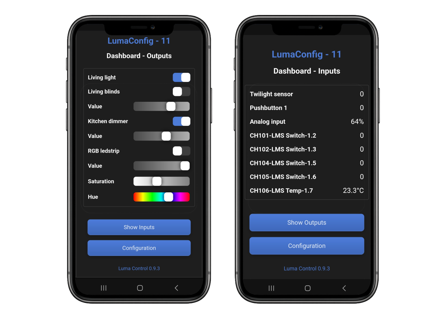
LumaConfig is a web application that allows you to operate and configure Luma One modules via smartphone, tablet, or computer. Because the application runs on the module itself, no separate app or software is required. LumaConfig can be accessed directly through a web browser (e.g., Google Chrome, Firefox, or Safari). This ensures long-term compatibility.
LumaConfig is een webapplicatie waarmee je Luma One-modules kunt bedienen en configureren via smartphone, tablet of computer. Omdat deze applicatie op de module zelf draait, is er geen aparte app of software nodig. LumaConfig is rechtstreeks bereikbaar via een webbrowser (bijv. Google Chrome, Firefox of Safari). Op deze manier blijft de compatibiliteit op de lange termijn gegarandeerd.
For simple installations where relay outputs are switched using push-buttons (including dimming), using LumaConfig is not required. In this case, the templates, learning mode, and on-module control can be used instead. More information can be found later in this manual.
Voor eenvoudige installaties waarbij er simpelweg relaisuitgangen geschakeld worden met drukknoppen (inclusief dimming), is het gebruik van LumaConfig niet vereist. In deze situatie kan er immers ook gewerkt worden met de templates, de leermodus en bediening op de module. Meer informatie hieromtrent vind je verder in deze handleiding.
To use more advanced features, LumaConfig is required. This includes network settings, integrations (MQTT, Modbus, DMX512), time functions, virtual channels, scenes, groups, and logic functions (AND, OR, XOR, NOT). More information is available in the LumaConfig manual. Click here
Voor het gebruik van de meer geavanceerde functies is het gebruik van LumaConfig wel vereist. Denk hierbij aan netwerkinstellingen, integraties (MQTT, modbus, DMX512), tijdsfuncties, virtuele kanalen, sferen, groepen, logische functies (AND, OR, XOR, NOT). Meer informatie vind je in de LumaConfig handleiding. Klik hier
Wiring diagrams
Aansluitschema's
Connection overview
Overzicht aansluitingen
- Push-buttons for manual operation and basic settings
- Drukknoppen voor manuele bediening en basisinstellingen
- 120 Ohm bus termination switch for LumaLink (left) and RS485 (right)
- Bus 120 Ohm terminatie switch voor LumaLink (links) en RS485 (rechts)
- Module and network status LEDs
- Module en netwerk status leds
- LumaLink bus connector; two connectors to simplify daisy-chaining (connected in parallel)
- LumaLink bus connector, twee connectoren om doorlussen te vereenvoudigen (parallel verbonden)
- LumaSense and RS485 connector
- LumaSense en RS485 connector
- Flex IO inputs/outputs, with the GND (-) connection on the far right
- Flex IO ingangen/uitgangen met de GND (-) connectie uiterst rechts
- Relay outputs, with the common connection on the far left
- Relais uitgangen met uiterst links de gemeenschappelijke connectie
- Optical 230 VAC input
- Optische 230 VAC ingang
- Additional common connection for relay outputs to simplify daisy-chaining
- Extra gemeenschappelijke connectie van relais uitgangen om doorlussen te vereenvoudigen
- Relay outputs with common connection on the far left and right
- Relais uitgangen met uiterst links en rechts de gemeenschappelijke connectie
- Relay outputs with common connection on the far left and right
- Relais uitgangen met uiterst links en rechts de gemeenschappelijke connectie
- Push-button inputs with the GND connection on the far left and right
- Druktoets ingangen met uiterst links en rechts de GND connectie
- Push-button inputs with the GND connection on the far left and right
- Druktoets ingangen met uiterst links en rechts de GND connectie
Mixed configuration
Gemengde configuratie
Below is a wiring diagram that highlights the different possibilities. The loads (in this case the lights, dimmers and LED strips) can be controlled by any push-button, including push-buttons connected to other modules on the LumaLink bus. The link between push-button and load can be configured using LumaConfig and/or the learning mode.
Hieronder een aansluitschema dat de verschillende mogelijkheden uitlicht. De belastingen (in dit geval de lichtpunten, dimmers en ledstrips), kunnen door eender welke drukknop bediend worden, ook door drukknoppen die verbonden zijn met andere modules op de LumaLink bus. De koppeling tussen drukknop en belasting kan gelegd worden met LumaConfig en/of de leermodus.
ℹ️ Information
ℹ️ Informatie
This is just an example configuration, there are many other possibilities. The function of each relay output or Flex IO channel can be configured freely.
Dit is slechts een voorbeeldconfiguratie, er zijn tal van andere mogelijkheden. De functionaliteit van elke relaisuitgang of Flex IO kanaal kan vrij geconfigureerd worden.
Lighting
Lichtpunten
Up to 16 lights (or other AC loads) can be controlled directly via the relay outputs. In addition, up to 4 extra AC loads can be connected by using external relays on the Flex IO channels (CH6-CH9).
Er kunnen maximaal 16 lichtpunten (of andere AC-belastingen) rechtstreeks aangestuurd worden met de relais uitgangen. Verder kunnen er nog maximaal 4 extra AC-belastingen aangesloten worden door externe relais aan te sluiten op de Flex IO kanalen (CH6-CH9).
Up to 4 lights (or other AC loads) can be controlled directly via the relay outputs. In addition, up to 4 extra AC loads can be connected by using external relays on the Flex IO channels (CH6-CH9).
Er kunnen maximaal 4 lichtpunten (of andere AC-belastingen) rechtstreeks aangestuurd worden met de relais uitgangen. Verder kunnen er nog maximaal 4 extra AC-belastingen aangesloten worden door externe relais aan te sluiten op de Flex IO kanalen (CH6-CH9).
Shutters / screens
Rolluiken / screens
Up to 8 shutter motors can be connected to the module’s relay outputs. The runtime can be learned using the learning mode or configured using LumaConfig.
Er kunnen maximaal 8 rolluikmotoren aangesloten worden op de relaisuitgangen van de module. De looptijd kan ingeleerd worden met de leermodus of kan ingesteld worden met LumaConfig.
Up to 2 shutter motors can be connected to the module’s relay outputs. The runtime can be learned using the learning mode or configured using LumaConfig.
Er kunnen maximaal 2 rolluikmotoren aangesloten worden op de relaisuitgangen van de module. De looptijd kan ingeleerd worden met de leermodus of kan ingesteld worden met LumaConfig.
This wiring diagram is intended for AC shutter motors that run on mains voltage. This circuit cannot be used for DC motors.
Deze schakeling is voor AC rolluikmotoren die werken op netspanning, voor DC-motoren kan deze schakeling niet gebruikt worden.
(*) Motor direction is as shown, but can be inverted if required in LumaConfig (option "INV=1"). (*) Enkel motoren ingetekend, vrije kanalen kunnen nog naar wens geconfigureerd worden.
(*) Draairichting motor zoals in afbeelding, maar kan indien nodig opgekeerd worden met LumaConfig (optie "INV=1").
LED lighting
LED verlichting
In the wiring diagram below, an RGBW LED strip is controlled via the Flex IO channels (CH6-CH9). A setup with single-color or RGB LED strips is also possible, unused Flex IO channels can then be configured for other functions.
In het aansluitschema hieronder wordt een RGBW ledstrip aangestuurd door de Flex IO kanalen (CH6-CH9). Een opstelling met single color of een RGB ledstrip is ook mogelijk, de niet gebruikte Flex IO kanalen kunnen dan geconfigureerd worden voor een andere functie.
Push-buttons
Drukknoppen
Up to 24 potential-free push-buttons can be connected directly to the module. Typically, the push-button inputs are used (CH33-CH52), but the Flex IO channels are also suitable (CH6-CH9). It is also possible to use LumaSense push-button interfaces (max. 19 interfaces). If the LumaSense bus is not used, one additional push-button can be connected to CH10.
Er kunnen tot 24 potentiaalvrije drukknoppen rechtstreeks aangesloten worden op de module. Typisch worden hier de drukknop ingangen voor gebruikt (CH33-CH52), maar ook de Flex IO kanalen zijn hiervoor geschikt (CH6-CH9). Het is ook mogelijk om met LumaSense drukknop-interfaces te werken (max 19 interfaces). Indien de LumaSense bus niet gebruikt wordt, kan er nog een extra drukknop aangesloten worden op CH10.
Up to 4 potential-free push-buttons can be connected directly to the module. It is also possible to use LumaSense push-button interfaces (max. 19 interfaces). If the LumaSense bus is not used, one additional push-button can be connected to CH10.
Er kunnen tot 4 potentiaalvrije drukknoppen rechtstreeks aangesloten worden op de module. Het is ook mogelijk om met LumaSense drukknop-interfaces te werken (max 19 interfaces). Indien de LumaSense bus niet gebruikt wordt, kan er nog een extra drukknop aangesloten worden op CH10.
This circuit can also be used to interface other digital sensors if they have a potential-free contact or an open-collector NPN output.
Deze schakeling kan ook worden gebruikt om andere digitale sensoren in te lezen indien ze beschikken over een potentiaalvrij contact of een open collector NPN-uitgang.
Sensors general
Sensoren algemeen
Digital sensors with potential-free contacts or open-collector NPN outputs (that sink current to GND) can be connected to the Flex IO channels, such as the digital sensor on CH8 (up to 4x). The push button inputs (up to 20x) can also be used for this purpose.
Digitale sensoren met potentiaalvrije contacten of open collector NPN-uitgangen (die stroom "sinken" naar GND), kunnen worden aangesloten op de Flex IO kanalen zoals de digitale sensor op CH8 (tot 4x). Ook de drukknop-ingangen (tot 20x) kunnen gebruikt worden.
Digital sensors with potential-free contacts or open-collector NPN outputs (that sink current to GND) can be connected to the Flex IO channels, such as the digital sensor on CH8 (up to 4x).
Digitale sensoren met potentiaalvrije contacten of open collector NPN-uitgangen (die stroom "sinken" naar GND), kunnen worden aangesloten op de Flex IO kanalen zoals de digitale sensor op CH8 (tot 4x).
The Flex IO channels (up to 4x) can also be used to interface sensors with a 0-10V output. If the sensor supply voltage matches the module supply voltage, the sensor can be powered from the module. (*1)
De Flex IO kanalen (tot 4x) zijn ook te gebruiken om sensoren met een 0-10V uitgang in te lezen. Indien de voedingsspanning van de sensor overeenstemt met de voedingsspanning van de module, kan de sensor vanuit de module gevoed worden. (*1)
Energy meters with an S0 pulse output can be connected to the Flex IO channels (up to 4x), see CH6 in the example below.
Energiemeters met een S0 pulsuitgang kunnen aangesloten worden op de Flex IO kanalen (tot 4x), zie CH6 in het voorbeeld hieronder.
(*1) If the sensor's current consumption allows it. (*) Beperkt aantal sensoren ingetekend, vrije kanalen kunnen nog naar wens geconfigureerd worden.
(*1) Indien het stroomverbruik van de sensor dit toelaat.
Actuators general
Actuatoren algemeen
Digital (binary) actuators can be connected to both the relay outputs and the Flex IO channels. The relay outputs (up to 16x) can switch higher current and are also suitable for AC loads. A drawback is that each relay group is tied to the actuator supply voltage due to a shared "COM" per relay group.
Digitale (binaire) actuatoren kunnen zowel op de relaisuitgangen als de Flex IO kanalen aangesloten worden. De relaisuitgangen (tot 16x) kunnen meer stroom schakelen en zijn ook geschikt voor AC-belastingen. Het nadeel is dan weer dat de volledige relaisgroep "vast zit" aan de voedingsspanning van de te schakelen actuator, dit doordat er een gemeenschappelijke "COM" is per relaisgroep.
Digital (binary) actuators can be connected to both the relay outputs and the Flex IO channels. The relay outputs (up to 4x) can switch higher current and are also suitable for AC loads. A drawback is that all relays are tied to the actuator supply voltage.
Digitale (binaire) actuatoren kunnen zowel op de relaisuitgangen als de Flex IO kanalen aangesloten worden. De relaisuitgangen (tot 4x) kunnen meer stroom schakelen en zijn ook geschikt voor AC-belastingen. Het nadeel is dan weer dat de spanning van alle relais "vast zit" aan de voedingsspanning van de te schakelen actuator.
Actuators connected to the Flex IO channels (up to 4x) are limited in current to 2.5A or 5A (*1) and are only suitable for DC loads. These channels include overcurrent protection that disables the output in case of overload. Flex IO channels are active-low NPN outputs, they sink current to GND (see CH7 below as an example). This sinking makes it possible for actuators to use a different supply voltage than the module itself. (*2)
Actuatoren aangesloten op de Flex IO kanalen (tot 4x), zijn beperkt in stroom tot 2.5A of 5A (*1) en zijn enkel geschikt voor DC-belastingen. Deze kanalen zijn voorzien van een overstroombeveiliging die de uitgang uitzet in geval van overbelasting. Flex IO kanalen zijn actief lage NPN-uitgangen, ze "sinken" de stroom als het ware naar GND, zie CH7 hieronder als voorbeeld. Dit "sinken" maakt dat de actuatoren met een andere voedingsspanning kunnen werken dan de module zelf. (*2)
The Flex IO channels (up to 4x) can also be used to control adjustable 0-10V actuators, see CH6 in the example below. In many cases this is used to control external 0-10V dimmers, but other applications are also possible.
De Flex IO kanalen (tot 4x) zijn ook te gebruiken om regelbare 0-10V actuatoren aan te sturen, zie CH6 in het voorbeeld hieronder. In veel gevallen wordt dit gebruikt om externe 0-10V dimmers aan te sturen, maar er zijn ook andere toepassingen mogelijk.
(*1) See technical specifications.
(*2) External supply required, max 26V DC. (*) Beperkt aantal actuatoren ingetekend, vrije kanalen kunnen nog naar wens geconfigureerd worden.
(*1) Zie technische specificaties.
(*2) Externe voeding nodig, max 26V DC.
Module power supply
Voeding module
The {{PRODUCT_NAME}} requires a stable DC power supply. This is typically provided via the LumaLink bus cable and can be daisy-chained to the next modules. (*1) Another option is powering the module via the LumaSense screw connector, this option is indicated in light green in the diagram below. Always provide a power supply that can deliver sufficient current for the number of connected modules, interfaces and other loads.
De {{PRODUCT_NAME}} heeft een stabiele DC voeding nodig. Deze gaat typisch via de LumaLink buskabel en is zo ook door te lussen naar de volgende modules. (*1) Een andere optie is de module voeden via de LumaSense schroefconnector, deze optie is in het lichtgroen aangeduid op onderstaand schema. Voorzie steeds een voeding die voldoende stroom kan leveren voor het aantal aangesloten modules, interfaces en andere belastingen.
LumaLink and LumaSense bus
LumaLink en LumaSense bus
Both the LumaLink and the LumaSense bus are typically wired using EIB cable. For LumaLink, the wiring rules are stricter. Preferably, the LumaLink bus should be installed in a daisy-chain topology (module-to-module), and the internal termination resistor should be enabled for only the first and last module on the bus.
Zowel de LumaLink als de LumaSense bus wordt typisch met EIB kabel uitgevoerd. Voor LumaLink zijn de bekabelingsregels wel strikter. Zo moet de LumaLink bus bij voorkeur in een "daisy-chain" busstructuur gelegd worden (doorlussen van module naar module), waarbij de interne terminatieweerstand geactiveerd moet worden voor enkel en alleen de 1ste en laatste module op de bus.
LumaSense is a slower bus and therefore does not require termination resistors. The bus topology does not matter (star, bus, ring, etc. are all allowed). The white conductor in EIB cable has no function here, but it may be looped through. This gives you the possibility to bring one signal directly to the module without using a LumaSense interface.
LumaSense is een tragere bus en heeft daarom geen terminatieweerstanden nodig. Verder maakt ook de busstructuur niet uit, dit mag een ster, bus, ringstructuur etc. zijn. De witte geleider in de EIB kabel heeft hier geen functie, maar kan wel worden doorgelust. Dit geeft je de mogelijkheid om één signaal rechtstreeks naar de module te brengen, zonder tussenkomt van een LumaSense interface.
ℹ️ Information
ℹ️ Informatie
The LumaLink bus requires a 120 Ohm termination resistor near the first and last module on the bus (*1). The {{PRODUCT_NAME}} includes an internal 120 Ohm resistor that can be enabled using the DIP switch on the front panel, see "2" on the image here.
De LumaLink bus heeft een 120 Ohm busterminatieweerstand nodig nabij de eerste en laatste module op de bus (*1). De {{PRODUCT_NAME}} heeft hiervoor een interne 120 Ohm weerstand die met de dip-switch op het frontpaneel geactiveerd kan worden, zie "2" op afbeelding hier.
Technical Specifications
Technische Specificaties
⚠️ Warning
⚠️ Waarschuwing
Failure to comply with the technical specifications may permanently damage the module.
Het niet naleven van de technische specificaties kan de module permanent beschadigen.
| General | Algemeen | ||||
|---|---|---|---|---|---|
| Dimensions | Afmetingen | 213 x 90mm (12x DIN) | 213 x 90mm (12x DIN) | ||
| Ambient temperature | Omgevingstemperatuur | 0° - 60°C, non-condensing. (*1) | 0° - 60°C, niet condenserend. (*1) | ||
| Supply voltage (V+/GND) | Voedingsspanning (V+/GND) | 13.5 - 26 VDC (*2) | 13.5 - 26 VDC (*2) | ||
| Power consumption | Verbruik |
10W max (all relays ON)
|
10W max (alle relais aan)
|
4W max (all relays ON)
|
4 W max (alle relais aan)
|
| Note | Opgelet | Outputs are switched off if the temperature inside the module becomes too high. | Uitgangen worden uitgeschakeld als de temperatuur in de module te hoog oploopt. | ||
(*2) Using a 12V power supply is also possible, but when using Flex IOs in 0-10V output mode, the output will be max. 9.5V instead of 10V.
(*1) De module gaat niet defect bij het overschrijden van de maximale temperatuur, maar zal wel in beveiliging gaan.
(*2) Het gebruik van een 12V voedingsspanning is ook mogelijk, maar bij gebruik van Flex IO's in 0-10V uitgang modus, zullen deze maximaal 9.5V uitgeven i.p.v. 10V.
Relay outputs
Relais uitgangen
| Relay outputsCH01-CH04/CH11-CH22 | Relais uitgangenCH01-CH04/CH11-CH22 | ||||
|---|---|---|---|---|---|
| Number | Aantal |
16x in total
|
16x in totaal
|
4x
|
4x
|
| Max combined current per group (COM) | Max. gecombineerde stroom per groep (COM) | 10A | 10A | ||
| Max load | Max. belasting |
250VAC/10A or 30VDC/10A (resistive)
|
250VAC/10A of 30VDC/10A (resistief)
|
||
| Max inrush current | Max. inschakelstroom | 80A (20ms) (*1) | 80A (20ms) (*1) | ||
| Lifetime | Levensduur | Min. 100 000 switching cycles | Min 100 000 schakelingen | ||
| Tightening torque | Aandraaimoment | 0.5Nm | 0.5Nm | ||
| Wire size | Draaddiameter | 0.2-4mm² | 0.2-4mm² | ||
| Strip length | Strip lengte | 8mm | 8mm | ||
| Note | Opgelet | Relay outputs are switched off if the temperature inside the module becomes too high. | Relais uitgangen worden uitgeschakeld als de temperatuur in de module te hoog oploopt. | ||
Push-button inputs
Drukknop ingangen
| Push-button inputs CH33-CH52 | Drukknop ingangen CH33-CH52 | ||
|---|---|---|---|
| Number | Aantal |
20x total
|
20x in totaal
|
| Input current | Ingangsstroom | 6mA @12V V+ 12mA @24V V+ |
6mA @12V V+ 12mA @24V V+ |
| Max cable length | Max. kabellengte | 30m | 30m |
| Min pulse width | Min. pulsbreedte | 30ms | 30ms |
| Wire size | Draaddiameter | 0.2-1.5mm² | 0.2-1.5mm² |
| Strip length | Strip lengte | 9mm | 9mm |
Optical inputs
Optische ingangen
| Optical input CH5 | Optische ingang CH5 | ||
|---|---|---|---|
| Number | Aantal | 1x | 1x |
| Input current | Ingangsstroom | 1.2mA @230V AC | 1.2mA @230V AC |
| Max cable length | Max. kabellengte | 30m | 30m |
| Min pulse width | Min. pulsbreedte | 20ms | 20ms |
| Max threshold voltage | Max. drempelspanning | 200V AC | 200V AC |
| Max input voltage | Max. ingangsspanning | 250V AC | 250V AC |
| Tightening torque | Aandraaimoment | 0.5Nm | 0.5Nm |
| Wire size | Draaddiameter | 0.2-4mm² | 0.2-4mm² |
| Strip length | Strip lengte | 8mm | 8mm |
Flex IOs
Flex IOs
| Configurable Flex IOs CH6-CH9 | Configureerbare Flex IOs CH6-CH9 | ||||
|---|---|---|---|---|---|
| Number | Aantal | 4x | 4x | ||
| LED PWM output mode (*1) | LED PWM uitgang modus (*1) |
|
|
|
|
| 0-10V output mode (*2) | 0-10V uitgang modus (*2) |
|
|
||
| Open-drain output mode (*3) (NPN output) |
Open drain uitgang modus (*3) (NPN uitgang) |
|
|
|
|
| Digital input mode (*4) | Digitale ingang modus (*4) |
|
|
||
| Max cable length | Max. kabellengte | 30m | 30m | ||
| Tightening torque | Aandraaimoment | 0.5Nm | 0.5Nm | ||
| Wire size | Draaddiameter | 0.2-2.5mm² | 0.2-2.5mm² | ||
| Strip length | Strip lengte | 8mm | 8mm | ||
| Extra | Extra | Short circuit protected in all modes. | Kortsluitvast in alle modi. | ||
| Note | Opgelet | Outputs are switched off if the temperature inside the module becomes too high. | Uitgangen worden uitgeschakeld als de temperatuur in de module te hoog oploopt. | ||
(*1) Kanaalfunctie ingesteld op "Out-Dimmer" in LumaConfig.
(*2) Channel function set to "Out-0-10V" or "Out-Dimmer 0-10V" in LumaConfig.
(*2) Kanaalfunctie ingesteld op "Out-0-10V" of "Out-Dimmer 0-10V" in LumaConfig.
(*3) Channel function set to "Out-Bin-*" in LumaConfig.
(*3) Kanaalfunctie ingesteld op "Out-Bin-*" in LumaConfig.
(*4) Channel function set to "In-Bin-*", "In-Pulse-Count" or "In-Utility-*" in LumaConfig.
(*4) Kanaalfunctie ingesteld op "In-Bin-*", "In-Pulse-Count" of "In-Utility-*" in LumaConfig.
LumaSense
LumaSense
| LumaSense masterCTRL/CH10 | LumaSense masterCTRL/CH10 | ||
|---|---|---|---|
| Max number of interfaces | Max. aantal interfaces | 19x | 19x |
| Max cable length | Max. kabellengte | 30m | 30m |
| Recommended cable type | Aanbevolen kabeltype | EIB | EIB |
| Bus termination | Terminatie bus | N/A | N.v.t. |
| Tightening torque | Aandraaimoment | 0.5Nm | 0.5Nm |
| Wire size | Draaddiameter | 0.2-1.5mm² | 0.2-1.5mm² |
| Strip length | Strip lengte | 8mm | 8mm |
LumaLink
LumaLink
| LumaLink | LumaLink | ||
|---|---|---|---|
| Max number of modules | Max. aantal modules | 64x | 64x |
| Max cable length | Max. kabellengte | 250m (*1) | 250m (*1) |
| Recommended cable type | Aanbevolen kabeltype | EIB | EIB |
| Bus termination | Terminatie bus | 120 Ohm | 120 Ohm |
| Wire size | Draaddiameter | 0.2-0.5mm² | 0.2-0.5mm² |
| Strip length | Strip lengte | 6mm | 6mm |
RS485
RS485
| RS485 | RS485 | ||
|---|---|---|---|
| Protocol | Protocol |
Mode configurable
|
Modus configureerbaar
|
| Max cable length | Max. kabellengte | 30m | 30m |
| Bus termination | Terminatie bus | 120R | 120R |
| Tightening torque | Aandraaimoment | 0.5Nm | 0.5Nm |
| Wire size | Draaddiameter | 0.2-2.5mm² | 0.2-2.5mm² |
| Strip length | Strip lengte | 8mm | 8mm |
Network
Netwerk
| Network | Netwerk | ||
|---|---|---|---|
| WiFi | WiFi | 2.4 GHz 802.11b/g/n | 2.4 GHz 802.11b/g/n |
| Ethernet (*1) | Ethernet (*1) | 10BaseT / 100BaseTX | 10BaseT / 100BaseTX |
| Network settings | Netwerk instellingen | DHCP or static | DHCP of statisch |
| Network time synchronization | Netwerk tijdsynchronisatie | SNTP | SNTP |
| MQTT | MQTT | LumaLink over MQTT | LumaLink over MQTT |
| Modbus TCP/IP | Modbus TCP/IP | Modbus RTU | Modbus RTU |
| HTTP server | HTTP server | LumaConfig | LumaConfig |
(*1) Module met ethernet ondersteuning op aanvraag.
Configuration templates
Configuratie templates
The Luma One XL is delivered with a default configuration (template mode 1). This configuration can be changed by loading a different template. This does not mean that the functionality of the module is limited to what is described in a template; a template is merely a starting configuration that can still be fully customized, for example using LumaConfig. The purpose of templates is to speed up commissioning by providing ready-made configurations for a number of commonly used applications.
De Luma One XL wordt met een standaardconfiguratie geleverd (template modus 1), deze configuratie kan aangepast worden door andere templates te laden. Dit wil echter niet zeggen dat de functionaliteit van de module beperkt is tot wat er beschreven is in de template, een template is enkel een startconfiguratie die nog naar eigen wens aan te passen is met bijvoorbeeld LumaConfig. De intentie van templates is het versnellen van de ingebruiksname door een template te voorzien voor een aantal veelgebruikte configuraties.
Template overview
Overzicht templates
| Template | Template | Push-buttons linked | Drukknoppen gekoppeld |
Relay function | Functie relais | Flex IO function | Functie Flex IO's |
|---|---|---|---|---|---|---|---|
| Mode 1 (factory) | Modus 1 (fabriek) | No | Nee | Lighting | Lichtpunt | LED PWM or 0-10V (*1) | LED PWM of 0-10V (*1) |
| Mode 2 | Modus 2 | Yes (*2) | Ja (*2) | Lighting | Lichtpunt | LED PWM or 0-10V (*1) | LED PWM of 0-10V (*1) |
| Mode 3 | Modus 3 | No | Nee | Shutter / screen | Rolluik | LED PWM or 0-10V (*1) | LED PWM of 0-10V (*1) |
| Mode 4 | Modus 4 | Yes (*2) | Ja (*2) | Shutter / screen | Rolluik | LED PWM or 0-10V (*1) | LED PWM of 0-10V (*1) |
(*2) Only valid for push-buttons on CH33-CH52; LumaSense or push-buttons connected to other modules are not automatically linked. (*1) Automatische detectie van ledstrips bij opstart, 0-10V uitgang wanneer geen leds gedetecteerd worden.
(*2) Enkel geldig voor drukknoppen op CH33-CH52, LumaSense of drukknoppen verbonden met andere modules worden niet automatisch gelinkt.
ℹ️ Information
ℹ️ Informatie
A template is nothing more than a starting configuration. It can always be fully customized, for example by using LumaConfig.
Een template is niet meer dan een startconfiguratie, deze kan nog volledig naar eigen wens aangepast worden met bijvoorbeeld LumaConfig.
Template mode 1 (factory)
Template modus 1 (fabriek)
Mode for switching lighting circuits. Push-button inputs (CH33-CH52) are NOT automatically linked to relay outputs in this mode. Push-buttons can be linked using the learning mode or with LumaConfig. Use the wiring diagram of mode 2.
Modus voor schakelen van lichtpunten. Drukknop ingangen (CH33-CH52) worden in deze modus NIET automatisch gekoppeld aan relais uitgangen. Drukknoppen kunnen wel ingeleerd worden met de leermodus, ook kan de LumaConfig gebruikt worden. Gebruik het aansluitschema van modus 2.
Template mode 2
Template modus 2
Mode for switching lighting circuits. Push-button inputs (CH33-CH52) are automatically linked to relay outputs in this mode. The linkage can still be adjusted using LumaConfig if required.
Modus voor schakelen van lichtpunten. Drukknop ingangen (CH33-CH52) worden in deze modus WEL automatisch gekoppeld aan relais uitgangen. De koppeling kan nog aangepast worden met LumaConfig indien nodig.
| Input | Ingang | Output | Uitgang | Function | Functie |
|---|---|---|---|---|---|
| Push-button CH10 (*1) | Drukknop CH10 (*1) | All outputs | Alle uitgangen | All off (double press) All on (long press) |
Alles uit (2x drukken) Alles aan (lang drukken) |
| Push-button CH6 | Drukknop CH6 | Relay CH1 | Relais CH1 | On/off | Aan/uit |
| Push-button CH7 | Drukknop CH7 | Relay CH2 | Relais CH2 | On/off | Aan/uit |
| Push-button CH8 | Drukknop CH8 | Relay CH3 | Relais CH3 | On/off | Aan/uit |
| Push-button CH9 | Drukknop CH9 | Relay CH4 | Relais CH4 | On/off | Aan/uit |
| Push-button CH33 | Drukknop CH33 | Relay CH11 | Relais CH11 | On/off | Aan/uit |
| Push-button CH34 | Drukknop CH34 | Relay CH12 | Relais CH12 | On/off | Aan/uit |
| Push-button CH35 | Drukknop CH35 | Relay CH13 | Relais CH13 | On/off | Aan/uit |
| Push-button CH36 | Drukknop CH36 | Relay CH14 | Relais CH14 | On/off | Aan/uit |
| Push-button CH37 | Drukknop CH37 | Relay CH15 | Relais CH15 | On/off | Aan/uit |
| Push-button CH38 | Drukknop CH38 | Relay CH16 | Relais CH16 | On/off | Aan/uit |
| Push-button CH39 | Drukknop CH39 | Relay CH1 | Relais CH1 | On/off | Aan/uit |
| Push-button CH40 | Drukknop CH40 | Relay CH2 | Relais CH2 | On/off | Aan/uit |
| Push-button CH41 | Drukknop CH41 | Relay CH3 | Relais CH3 | On/off | Aan/uit |
| Push-button CH42 | Drukknop CH42 | Relay CH4 | Relais CH4 | On/off | Aan/uit |
| Push-button CH43 | Drukknop CH43 | Relay CH17 | Relais CH17 | On/off | Aan/uit |
| Push-button CH44 | Drukknop CH44 | Relay CH18 | Relais CH18 | On/off | Aan/uit |
| Push-button CH45 | Drukknop CH45 | Relay CH19 | Relais CH19 | On/off | Aan/uit |
| Push-button CH46 | Drukknop CH46 | Relay CH20 | Relais CH20 | On/off | Aan/uit |
| Push-button CH47 | Drukknop CH47 | Relay CH21 | Relais CH21 | On/off | Aan/uit |
| Push-button CH48 | Drukknop CH48 | Relay CH22 | Relais CH22 | On/off | Aan/uit |
| Push-button CH49 | Drukknop CH49 | Flex IO CH6 | Flex IO CH6 | On/off (short press) Dimming (long press) |
Aan/uit (kort drukken) Dimmen (lang drukken) |
| Push-button CH50 | Drukknop CH50 | Flex IO CH7 | Flex IO CH7 | On/off (short press) Dimming (long press) |
Aan/uit (kort drukken) Dimmen (lang drukken) |
| Push-button CH51 | Drukknop CH51 | Flex IO CH8 | Flex IO CH8 | On/off (short press) Dimming (long press) |
Aan/uit (kort drukken) Dimmen (lang drukken) |
| Push-button CH52 | Drukknop CH52 | Flex IO CH9 | Flex IO CH9 | On/off (short press) Dimming (long press) |
Aan/uit (kort drukken) Dimmen (lang drukken) |
(*1) CH10 kan niet als drukknop ingang gebruikt worden in combinatie met de LumaSense bus.
Wiring diagram mode 2
Aansluitschema modus 2
(*2) Template mode 1: Push-buttons must still be linked to outputs (learning mode or LumaConfig), no fixed mapping.
Template mode 2: Push-button O11 (CH33) is pre-linked to output CH11, etc. (*1) Flex IO 0-10V/PWM automatische detectie: tot 4x 0-10V uitgang, tot 4x led PWM uitgang of een combinatie.
(*2) Template modus 1: Drukknoppen nog te koppelen aan uitgangen ( of LumaConfig), geen vaste mapping.
Template modus 2: Drukknop O11 (CH33) reeds gekoppeld aan lichtpunt CH11 etc.
Template mode 3
Template modus 3
Shutter/screen mode. Push-button inputs (CH33-CH52) are NOT automatically linked to relay outputs in this mode. Push-buttons can be linked using the learning mode or with LumaConfig. Use the wiring diagram of mode 4. Although this mode is intended for shutter motors, 0-10V dimmers or LED lighting can still be connected to the Flex IO channels (CH6-CH9).
Rolluik/screen modus. Drukknop ingangen (CH33-CH52) worden in deze mode NIET automatisch gekoppeld aan relais uitgangen. Drukknoppen kunnen wel ingeleerd worden met de leermodus, ook kan de LumaConfig gebruikt worden. Gebruik het aansluitschema van modus 4. Hoewel deze modus voor rolluikmotoren bedoeld is, kunnen er nog steeds 0-10V dimmers of leds aangesloten worden op de Flex IO kanalen (CH6-CH9).
Template mode 4
Template modus 4
Shutter/screen mode. Push-button inputs (CH33-CH52) are automatically linked to relay outputs in this mode. The linkage can still be adjusted using LumaConfig if required. Although this mode is intended for shutter motors, 0-10V dimmers or LED lighting can still be connected to the Flex IO channels (CH6-CH9).
Rolluik/screen modus. Drukknop ingangen (CH33-CH52) worden in deze mode WEL automatisch gekoppeld aan relais uitgangen. De koppeling kan nog aangepast worden met LumaConfig indien nodig. Hoewel deze modus voor rolluikmotoren bedoeld is, kunnen er nog steeds 0-10V dimmers of leds aangesloten worden op de Flex IO kanalen (CH6-CH9).
| Input | Ingang (*2) | Output | Uitgang | Function | Functie |
|---|---|---|---|---|---|
| Push-button CH10 (*1) | Drukknop CH10 (*1) | All outputs | Alle uitgangen | All off (double press) All on (long press) |
Alles uit (2x drukken) Alles aan (lang drukken) |
| Push-button CH6 | Drukknop CH6 | Relay CH1/CH2 | Relais CH1/CH2 | Shutter up/down | Rolluik omhoog/omlaag |
| Push-button CH8 | Drukknop CH8 | Relay CH3/CH4 | Relais CH3/CH4 | Shutter up/down | Rolluik omhoog/omlaag |
| Push-button CH33 | Drukknop CH33 | Relay CH11/CH12 | Relais CH11/CH12 | Shutter up/down | Rolluik omhoog/omlaag |
| Push-button CH35 | Drukknop CH35 | Relay CH13/CH14 | Relais CH13/CH14 | Shutter up/down | Rolluik omhoog/omlaag |
| Push-button CH37 | Drukknop CH37 | Relay CH15/CH16 | Relais CH15/CH16 | Shutter up/down | Rolluik omhoog/omlaag |
| Push-button CH39 | Drukknop CH39 | Relay CH1/CH2 | Relais CH1/CH2 | Shutter up/down | Rolluik omhoog/omlaag |
| Push-button CH41 | Drukknop CH41 | Relay CH3/CH4 | Relais CH3/CH4 | Shutter up/down | Rolluik omhoog/omlaag |
| Push-button CH43 | Drukknop CH43 | Relay CH17/CH18 | Relais CH17/CH18 | Shutter up/down | Rolluik omhoog/omlaag |
| Push-button CH45 | Drukknop CH45 | Relay CH19/CH20 | Relais CH19/CH20 | Shutter up/down | Rolluik omhoog/omlaag |
| Push-button CH47 | Drukknop CH47 | Relay CH21/CH22 | Relais CH21/CH22 | Shutter up/down | Rolluik omhoog/omlaag |
| Push-button CH49 | Drukknop CH49 | Flex IO CH6 | Flex IO CH6 | Light on/off (short press) Dimming (long press) |
Licht aan/uit (kort drukken) Dimmen (lang drukken) |
| Push-button CH50 | Drukknop CH50 | Flex IO CH7 | Flex IO CH7 | Light on/off (short press) Dimming (long press) |
Licht aan/uit (kort drukken) Dimmen (lang drukken) |
| Push-button CH51 | Drukknop CH51 | Flex IO CH8 | Flex IO CH8 | Light on/off (short press) Dimming (long press) |
Licht aan/uit (kort drukken) Dimmen (lang drukken) |
| Push-button CH52 | Drukknop CH52 | Flex IO CH9 | Flex IO CH9 | Light on/off (short press) Dimming (long press) |
Licht aan/uit (kort drukken) Dimmen (lang drukken) |
(*2) Er wordt 1 drukknop gekoppeld aan elke rolluik uitgang (bestaande uit 2 relais uitgangen). Hierdoor zijn er 8 vrije drukknop ingangen, deze kunnen elders nog gebruikt worden, bijvoorbeeld om uitgangen op andere LumaLink devices te bedienen.
(*2) Indien gewenst kan een rolluik uitgang ook met 2 drukknoppen bediend worden (omhoog en omlaag met afzonderlijke drukknop). (*1) CH10 cannot be used as a push-button input when the LumaSense bus is in use.
(*2) One pushbutton is linked to each shutter output (consisting of 2 relay outputs). This leaves 8 free pushbutton inputs, which can be used elsewhere, for example to control outputs on other LumaLink devices.
(*2) If required, a shutter output can also be controlled using 2 pushbuttons (separate buttons for up and down).
Wiring diagram mode 4
Aansluitschema modus 4
(*2) Template mode 3: Push-buttons must still be linked to outputs (learning mode or LumaConfig), no fixed mapping.
Template mode 4: Push-button O11 (CH33) is pre-linked to shutter motor CH11/CH12, etc. (*1) Flex IO 0-10V/PWM automatische detectie, tot 4x 0-10V uitgang, tot 4x led PWM uitgang of een combinatie.
(*2) Template modus 3: Drukknoppen nog te koppelen aan uitgangen (leermodus of LumaConfig), geen vaste volgorde.
Template modus 4: Drukknop O11 (CH33) reeds gekoppeld aan motor CH11/CH12 etc.
Usage
Gebruik
Remove front panel
Verwijderen frontpaneel
Remove the front panel to access the control buttons and the bus termination switches. Use a flat-head screwdriver and carefully pry the front panel upwards at the indicated locations shown below.
Het frontpaneel dient verwijderd te worden om bij de bedieningselementen en bus terminatieschakelaars te kunnen. Dit doe je door met een platte schroevendraaier op de aangegeven locaties hieronder het frontpaneel omhoog te wippen.
Status LEDs
Status leds
The two status LEDs on the front panel provide a quick indication of the module status.
De twee status leds op het frontpaneel geven snel een indicatie van de staat van de module.
| Heartbeat LED (left) | Heartbeat led (links) | Network LED (right) | Netwerk led (rechts) | Meaning | Betekenis |
|---|---|---|---|---|---|
| Off | Uit | On | Aan | Module startup | Module opstart |
| On | Aan | — | — | Normal operation | Normale werking |
| Blinking, long: 1, short: 1 | Knipperend, lang: 1, kort: 1 | — | — | Learning mode active | Leermode actief |
| Blinking, long: 2, short: 1 | Knipperend, lang: 2, kort: 1 | Fast blinking | Snel knipperend | General fault | Algemene fout |
| Blinking, long: 2, short: 2 | Knipperend, lang: 2, kort: 2 | Fast blinking | Snel knipperend | Overtemperature | Te hoge temperatuur |
| Blinking, long: 2, short: 3 | Knipperend, lang: 2, kort: 3 | Fast blinking | Snel knipperend | Supply voltage fault | Voedingsspanning fout |
| — | — | On | Aan | WiFi or Ethernet connected | Wifi of ethernet verbonden |
| — | — | Off | Uit | No connection via WiFi or Ethernet | Geen verbinding via Wifi of ethernet |
| — | — | Blinking, long: 0, short: 2 | Knipperend, lang: 0, kort: 2 | LumaConfig temporarily active via WiFi AP | LumaConfig (tijdelijk) actief via Wifi AP |
| — | — | Blinking, long: 0, short: 1 | Knipperend, lang: 0, kort: 1 | LumaConfig temporarily active via WiFi or Ethernet | LumaConfig (tijdelijk) actief via Wifi of ethernet |
Manual control
Manuele bediening
The three push-buttons on the front panel can be used to manually control the module.
De drie drukknoppen op het frontpaneel kunnen worden gebruikt om de module manueel te bedienen.
No channel selected
Geen kanaal geselecteerd
If no channel is selected (no blinking CHx LED), the buttons perform general module actions.
Indien er geen kanaal geselecteerd (er is geen knipperende CHx led), worden de drukknoppen gebruikt voor algemene module-acties.
| Button | Druktoets | Condition | Voorwaarde | Action | Actie |
|---|---|---|---|---|---|
| ➡️ | ➡️ | Short press | Kort drukken | Select channel to control | Selectie te bedienen kanaal |
| ➡️ | ➡️ | Long press (+5s) (*1) | Lang drukken (+5s) (*1) | Restart module in wifi AP mode and activate LumaConfig | Herstart module in wifi AP modus en activeer LumaConfig |
| ➡️ | ➡️ | Long press (+10s) (*2) | Lang drukken (+10s) (*2) | Restart module | Herstart module |
| ➡️ | ➡️ | Long press (+30s) (*3) | Lang drukken (+30s) (*3) | Reset WiFi settings | Reset WiFi instellingen |
| ➡️ | ➡️ | Long press (+60s) (*4) | Lang drukken (+60s) (*4) | Restore factory settings | Herstel fabrieksinstellingen |
| ⬆️ | ⬆️ | Short or long press | Kort of lang drukken | Show module address (*5) | Toon module adres (*5) |
| ⬇️ | ⬇️ | Short or long press | Kort of lang drukken | Show module template | Toon module template |
| ⬇️ + ⬆️ | ⬇️ + ⬆️ | Long press (+1s) | Lang drukken (+1s) | Activate LumaConfig temporarily | Activeer LumaConfig tijdelijk |
| ⬇️ + ⬆️ | ⬇️ + ⬆️ | Long press (+5s) | Lang drukken (+5s) | Allow firmware upload temporarily (*6) | Laat tijdelijk firmware upload toe (*6) |
| ⬇️ + ⬆️ | ⬇️ + ⬆️ | Long press (+10s) | Lang drukken (+10s) | Activate LumaConfig and allow firmware upload temporarily for all wired modules (*6) | Activeer LumaConfig en laat firmware upload tijdelijk toe voor alle bedrade modules (*6) |
(*2) Keep holding until the heartbeat (MOD) LED turns on again.
(*3) Keep holding until the heartbeat (MOD) LED blinks quickly.
(*4) Keep holding until the heartbeat (MOD) LED blinks even faster. The LumaLink bus address will not be reset. This only works the first 5 mins after startup.
(*5) The channel LED shows the address, e.g. if CH3 is on, the bus address is 3. Addresses above 9 are not shown; use LumaConfig for those.
(*6) Heartbeat (MOD) LED blinks quickly, firmware upload via LumaConfig will be allowed during 60s. (*1) Blijven indrukken tot heartbeat (MOD) led uitgaat.
(*2) Blijven indrukken tot heartbeat (MOD) led weer aangaat.
(*3) Blijven indrukken tot heartbeat (MOD) led snel knippert.
(*4) Blijven indrukken tot heartbeat (MOD) led nog sneller knippert. LumaLink busadres wordt niet gereset. Dit werkt enkel de eerste 5 min. na opstarten.
(*5) Kanaal-led geeft adres weer, vb: als CH3 brandt, is het busadres 3. Adressen boven 9 worden niet weergeven, gebruik hiervoor LumaConfig.
(*6) Heartbeat (MOD) led gaat snel knipperen, firmware upload via LumaConfig wordt toegelaten gedurende 60s.
Channel selected
Kanaal geselecteerd
If a channel is selected (a CHx LED is blinking), the buttons perform channel actions. After 10 seconds without activity, the selected channel is automatically deselected.
Indien er wel een kanaal geselecteerd is (er is een knipperende CHx led), worden de drukknoppen gebruikt voor kanaal-acties. Na 10 seconden zonder actie wordt het geselecteerde kanaal automatisch gedeselecteerd.
| Button | Druktoets | Condition | Voorwaarde | Action | Actie |
|---|---|---|---|---|---|
| ➡️ | ➡️ | Short press | Kort drukken | Select next channel | Selecteer volgende kanaal |
| ⬆️ | ⬆️ | Short press | Kort drukken | Switch ON | Schakel aan |
| ⬇️ | ⬇️ | Short press | Kort drukken | Switch OFF | Schakel uit |
| ⬆️ | ⬆️ | Long press (+2s) (*1) | Lang drukken (+2s)(*1) | Enable learning mode for channel | Activeer leermodus voor kanaal |
| ⬇️ | ⬇️ | Long press (+2s) | Lang drukken (+2s) | Disable learning mode for channel | Deactiveer leermodus voor kanaal |
Change configuration template
Configuratie template aanpassen
If needed, you can change the module’s initial configuration by applying configuration templates. An overview of the available templates can be found here.
Indien gewenst kan de startconfiguratie van de module aangepast worden door configuratie templates toe te passen. Hier vind je een overzicht van de verschillende templates.
- Press ⬇️ to check the current template (CH2 LED = template mode 2, etc.).
- Press ⬇️ and then ➡️ to change the template. Hold both buttons for 10 seconds until the CHx LED shifts by one position.
- Keep holding ⬇️. By briefly pressing ➡️, you can now cycle through the templates.
- Release both buttons when the desired template is selected.
- The module will automatically restart to apply the template.
- Druk ⬇️ om de huidige template te controleren (CH2 led = template mode 2 etc.).
- Druk ⬇️ en daarna ➡️ om de template aan te passen. Beide toetsen 10 seconden ingedrukt houden tot CHx LED met 1 positie verspringt.
- Blijf ⬇️ indrukken. Door kort te drukken op ➡️, kan je nu door de verschillende templates gaan.
- Laat beide toetsen los indien de gewenste template geselecteerd is.
- De module zal nu automatisch herstarten om de template toe te passen.
Set LumaLink bus address
LumaLink busadres instellen
Using manual control you can set a bus address from 1 to 9. If you need more than 9 addresses, use LumaConfig to set an address of 10 or higher.
Met de manuele bediening kan je een busadres van 1 tot en met 9 instellen. Kom je niet toe met 9 adressen, gebruik dan LumaConfig om een adres van 10 of meer in te stellen.
- Press ⬆️ to check the current bus address (CH2 LED = address 2, etc.).
- Press ⬆️ and then ➡️ to change the bus address. Hold both buttons for 10 seconds until the CH LED shifts by one position.
- Keep holding ⬆️. By briefly pressing ➡️, you can now cycle through the addresses.
- Release both buttons when the desired address is selected.
- The module will automatically restart to apply the new address.
- Druk ⬆️ om het huidige bus adres te controleren (CH2 led = adres 2 etc.).
- Druk ⬆️ en daarna ➡️ om het bus adres aan te passen. Beide toetsen 10 seconden ingedrukt houden tot CH LED met 1 positie verspringt.
- Blijf ⬆️ indrukken. Door kort te drukken op ➡️, kan je nu door de verschillende adressen gaan.
- Laat beide toetsen los indien het gewenste adres geselecteerd is.
- De module zal nu automatisch herstarten om het nieuwe adres toe te passen.
Learn push-buttons
Inleren drukknoppen
Push-buttons can be easily linked to outputs using the learning mode. If needed, you can later edit these links in LumaConfig—for example to change a single press to a double press, long press, or timer function. More information is available in the LumaConfig manual here.
Drukknoppen kunnen eenvoudig worden gekoppeld met uitgangen met behulp van de leermodus. Deze koppelingen kan je indien nodig nog bewerken met LumaConfig, bijvoorbeeld om een enkele druk aan te passen naar een dubbele druk, lange druk of timer functie. Meer informatie in de LumaConfig handleiding hier.
Link a push button
Drukknop koppelen
- Short press ➡️ to select the desired output.
- Long press ⬆️ until learning mode is enabled for the selected output.
- Press and hold the push button you want to link to the selected output. Release the button when the output toggles.
- Now briefly press the same push button once more. The link is created and you can control the output.
- Druk kort ➡️ om de gewenste uitgang te selecteren.
- Druk lang ⬆️ tot de leermodus geactiveerd wordt voor de geselecteerde uitgang.
- Druk lang op de drukknop die je met de geselecteerde uitgang wil koppelen. Laat de drukknop los als de uitgang toggelt.
- Druk nu nog een keer kort op de drukknop die je wil koppelen, nu is de koppeling gelegd en kan je de uitgang bedienen.
Unlink a push button
Drukknop ontkoppelen
- Short press ➡️ to select the desired output.
- Long press ⬆️ until learning mode is enabled for the selected output.
- Press and hold the push button you want to unlink from the selected output. Do NOT release the button when the output toggles the first time.
- Release the push button when the output toggles a second time.
- Now briefly press the same push button once more. The link is removed.
- Druk kort ➡️ om de gewenste uitgang te selecteren.
- Druk lang ⬆️ tot de leermodus geactiveerd wordt voor de geselecteerde uitgang.
- Druk lang op de drukknop die je met de geselecteerde uitgang wil ontkoppelen. Laat de drukknop NIET los als de uitgang een 1ste keer toggelt.
- Laat de drukknop los als de uitgang voor een 2de keer toggelt.
- Druk nu nog een keer kort op de drukknop die je wil ontkoppelen, de koppeling is nu verwijderd.
Safety
Veiligheid
⚠️ Warning
⚠️ Waarschuwing
- Do not work on the module without switching off the power supply.
- The module must only be installed and maintained by a certified electricien.
- Always follow the applicable installation regulations of the country of concern.
- The relays inside the module are not fused, always install an external circuit breaker of max. 10A on the common (COM) connection.
- Only relay outputs and CH5 are galvanically isolated, all other connections to the module must be SELV.
- Werk niet aan de module zonder de spanning uit te schakelen.
- De module mag uitsluitend worden geïnstalleerd en onderhouden door een erkend elektricien.
- Volg te allen tijde de geldende installatievoorschriften van het betreffende land.
- Relais in de module zijn niet afgezekerd, plaats steeds een externe automaat van 10A max in de gemeenschapplijke aansluiting (COM).
- Alleen de relaisuitgangen en CH5 zijn galvanisch geisoleerd, alle andere verbindingen met de module moeten SELV zijn.
Standards
Normeringen
| General | Algemeen | ||
|---|---|---|---|
| Safety class | Veiligheidsklasse | II | II |
| Ingress protection | Beschermingsgraad | IP20 | IP20 |
| Standard | Norm | Designed according IEC-60730-1 | Volgens IEC-60730-1 |
| Pollution degree | Vervuilingsgraad | 2 | 2 |
| Overvoltage category | Overspanningscategorie | III | III |
| Certificates | Certificaten | CE | CE |