Product information
Productinformatie
 |
Product name: LumaConfig | Productnaam: LumaConfig |
| Model: Luma One (XL) | Model: Luma One (XL) | |
| Document version: 2026.01 | Documentversie: 2026.01 |
Table of contents
Inhoudsopgave
Product description
Productbeschrijving
LumaConfig is a web-based application used to configure and control Luma One modules from a smartphone, tablet, or computer. Because the application runs directly on the module itself, no separate app or software installation is required. LumaConfig is accessed through a standard web browser (e.g. Google Chrome, Firefox, or Safari), ensuring long-term compatibility.
Modules can also be configured and used without LumaConfig (see templates and learning mode in the technical manual), but this is limited to basic functionality. For advanced features, the use of LumaConfig is essential. Below is a brief overview of what LumaConfig can be used for:
LumaConfig is een webapplicatie waarmee je Luma One-modules kunt bedienen en configureren via smartphone, tablet of computer. Omdat deze applicatie op de module zelf draait, is er geen aparte app of software nodig. LumaConfig is rechtstreeks bereikbaar via een webbrowser (bijv. Google Chrome, Firefox of Safari). Op deze manier blijft de compatibiliteit op de lange termijn gegarandeerd.
Modules kunnen ook zonder LumaConfig geconfigureerd en gebruikt worden (zie templates en leermodus in de technische handleiding), maar dat beperkt zich tot basisfunctionaliteit. Voor geavanceerde functies is het gebruik van LumaConfig essentieel. Hieronder vind je een beknopt overzicht van de mogelijkheden van LumaConfig:
- Dashboard
- Control outputs
- Monitor inputs
- Physical inputs and outputs
- Set function (lighting, shutters/screens, 0-10V, push-button, …)
- Assign names and group names
- Manually link triggers and actions (e.g. push-buttons)
- Virtual outputs
- Use as logic function (AND, OR, XOR, NOT)
- Send group and scene commands
- Extend the number of triggers for physical outputs
- Assign names and group names
- Manually link triggers and actions (e.g. push-buttons)
- Astronomical clock and time functions
- Sunrise and sunset based on location
- Automatic time synchronization via the network
- Module settings
- Wi-Fi, MQTT, Modbus, DMX512, etc.
- LumaLink bus tools
- Bus communication logger
- Testing scenes and groups
- Learning mode
- Automatically link push-buttons (also for virtual outputs)
- Dashboard
- Bedienen van uitgangen
- Monitoren van ingangen
- Fysieke in- en uitgangen
- Functie instellen (lichtpunt, screens, 0-10V, drukknop, …)
- Namen en groepsnamen toekennen
- Triggers en acties handmatig koppelen (bv. drukknoppen)
- Virtuele uitgangen
- Gebruik als logische functie (AND, OR, XOR, NOT)
- Groeps- en sfeercommando's uitsturen
- Aantal triggers van fysieke uitgangen uitbreiden
- Namen en groepsnamen toekennen
- Triggers en acties handmatig koppelen (bv. drukknoppen)
- Astroklok en tijdsfuncties
- Zonsopgang en zonsondergang op basis van locatie
- Automatische tijdsynchronisatie via netwerk
- Module instellingen
- Wi-Fi, MQTT, Modbus, DMX512 etc.
- LumaLink bustools
- Buscommunicatie-logger
- Testen van sferen en groepen
- Leermodus
- Voor het automatisch koppelen van drukknoppen (ook voor virtuele uitgangen)
LumaLink Basics
LumaLink Basics
LumaLink and LumaSense are bus systems used to connect modules, push-button interfaces and sensors without the need for a central controller. This creates a decentralized system in which each module contains its own program logic (triggers and actions). To configure the modules correctly, it is important to understand the LumaLink and LumaSense concepts.
LumaLink en LumaSense zijn bussystemen om modules, drukknoppen en sensoren met elkaar te koppelen, zonder centrale controller. Je krijgt zo een decentraal systeem waarbij elke module zijn eigen programmeercode (triggers en acties) bevat. Om de modules correct te configureren is het belangrijk het LumaLink- en LumaSense concept goed te begrijpen.
LumaLink
LumaLink
LumaLink is a 4-wire bus system that allows multiple modules to be interconnected. Information about inputs and outputs is exchanged between all modules connected to the LumaLink bus. A push-button, for example, does not need to be wired directly to the module that controls the desired output. Inputs and outputs can be linked using LumaConfig or with the built-in learning mode.
LumaLink is een 4-draads bussysteem waarmee verschillende modules met elkaar verbonden kunnen worden. Op deze manier wordt er informatie over in- en uitgangen uitgewisseld met alle verbonden modules op de LumaLink-bus. Een drukknop hoeft dus bijvoorbeeld niet verbonden te zijn met de module waarop de gewenste uitgang zich bevindt. Het koppelen van ingangen met uitgangen gebeurt met LumaConfig of met de ingebouwde leermodus.
In general there are two types of LumaLink messages: STATUS and EVENT.
Event messages are sent when an input or output changes state, for example when a push-button is pressed.
Status messages are sent periodically (at least once per minute).
Outputs can then be configured to perform an action (toggle, on, off, etc.) when a specific trigger is received
(a LumaLink event or status message).
In het algemeen zijn er twee types LumaLink-berichten: STATUS en EVENT.
Event-berichten worden verstuurd bij een verandering van de status van een ingang of uitgang, bijvoorbeeld bij een druk op een drukknop.
Status-berichten worden periodiek verstuurd (minstens één keer per minuut).
Uitgangen kunnen vervolgens geconfigureerd worden om een bepaalde actie (toggle, aan, uit, etc.) uit te voeren bij het ontvangen van een
bepaalde trigger (een LumaLink event- of statusbericht).
LumaSense
LumaSense
LumaSense is a 3-wire bus system specifically designed for sensors such as push-button interfaces. LumaSense operates at a lower speed than LumaLink, which offers several advantages. For example, no termination resistors are required, standard EIB cable can be used, and stubs or star topologies are not a problem. LumaSense messages received by the Luma One module are automatically converted to LumaLink messages (status and event), allowing all LumaLink modules to access the status of sensors even when they are not directly connected.
LumaSense is een 3-draads bussysteem specifiek voor sensoren zoals drukknopinterfaces. De snelheid van LumaSense ligt lager dan die van LumaLink en dat heeft enkele voordelen. Zo zijn er bijvoorbeeld geen terminatieweerstanden nodig en kan er met EIB-kabel gewerkt worden, verder vormen ook stubs of sterverbindingen geen probleem. LumaSense-berichten van de sensoren worden door de Luma One module steeds omgezet naar LumaLink-berichten (status en event), zo hebben alle LumaLink modules ook toegang tot de status van sensoren waarmee ze niet rechtstreeks verbonden zijn.
You may also choose to work without push-button and LumaSense interfaces and connect the push-buttons directly to the module. This is simpler, but LumaSense is more flexible and easier to expand later on.
Je kunt er ook voor kiezen om zonder drukknopinterfaces te werken en de drukknoppen rechtstreeks met de module te verbinden (bv. met meeraderige kabel). In dat geval is er geen LumaSense-bus nodig. Een systeem met drukknopinterfaces en LumaSense is echter flexibeler en later makkelijker uit te breiden.
Voorbeeld
Example
Below is an example configuration to illustrate a number of possibilities.
Hieronder een voorbeeldconfiguratie om een aantal mogelijkheden toe te lichten.
-
Ingangen op module A (adres 1) bedienen uitgangen op module B (adres 2) en omgekeerd.
- CH6 op beide modules bedient CH1 relais op module A
- CH108 op drukknopinterface bedient CH2 relais op module A
- CH7 op 2de module bedient CH2 relais op module A
-
Inputs on module A (address 1) control outputs on module B (address 2) and vice versa.
- CH6 on both modules controls relay CH1 on module A
- CH108 on the push-button interface controls relay CH2 on module A
- CH7 on module 2 controls relay CH2 on module A
-
Virtueel kanaal CH64 stuurt een LumaLink "alles uit"-bericht. Alle modules/uitgangen op de bus reageren hierop.
- Bij drukken op CH7 op module A
- Bij drukken op CH100 op drukknopinterface A
-
Virtual channel CH64 sends a LumaLink "all off" message. All modules/outputs on the bus react to this.
- When pressing CH7 on module A
- When pressing CH100 on push-button interface A
-
Virtueel kanaal CH57 stuurt een LumaLink "groep living aan"-bericht.
Alle modules/uitgangen op de bus reageren hierop wanneer de betreffende uitgang "living" als groepsnaam heeft.
In dit geval zullen CH2 op de 1ste en CH1 op de 2de module inschakelen.
- Bij drukken op CH8 op module A
- Bij drukken op CH109 op drukknopinterface B
-
Virtual channel CH57 sends a LumaLink "group living on" message.
All modules/outputs on the bus respond to this when the relevant output has "living" as its group name.
In this case, CH2 on module 1 and CH1 on module 2 will switch on.
- When pressing CH8 on module A
- When pressing CH109 on push-button interface B
Initial setup
Eerste ingebruikname
Follow the steps below to prepare new modules for operation and to complete the initial system configuration.
Volg onderstaande stappen om nieuwe modules gebruiksklaar te maken en de initiële systeemconfiguratie uit te voeren.
- Assign a unique LumaLink bus address to each module using the buttons on the front panel. See the technical manual for the procedure.
- Stel via de bediening op het frontpaneel een uniek LumaLink-busadres in voor elke module. Raadpleeg de technische handleiding voor de procedure.
-
During initial setup, the module does not yet have any network configuration.
Therefore, connect to the module by placing it into
AP mode. AP mode creates a temporary Wi-Fi network for direct access without using a router or local network. See Connect in AP mode. -
Bij de eerste ingebruikname heeft de module nog geen netwerkconfiguratie.
Maak daarom verbinding met de module via
AP-modus. AP-modus maakt een tijdelijk Wi-Fi-netwerk aan waarmee je rechtstreeks verbinding kunt maken zonder router of lokaal netwerk. Zie Verbinden in AP-modus. - Complete the remaining configuration using LumaConfig. Typical tasks include configuring module settings, linking inputs to outputs, assigning channel and group names, and configuring triggers. See Quick Start.
- Rond de resterende configuratie af via LumaConfig. Typische taken zijn het instellen van module-instellingen, het koppelen van in- en uitgangen, het toekennen van kanaal- en groepsnamen, en het configureren van triggers. Zie Quick Start.
ℹ️ Configuration tips
ℹ️ Configuratietips
Modules connected to the same LumaLink bus can synchronize their configuration (including network settings). As a result, only the first module typically needs to be placed into AP mode. The remaining modules automatically receive the required settings through the LumaLink bus.
Modules die op dezelfde LumaLink-bus aangesloten zijn, kunnen hun configuratie synchroniseren (inclusief netwerkinstellingen). Hierdoor hoeft doorgaans alleen de eerste module in AP-modus gezet te worden. De overige modules ontvangen de benodigde instellingen automatisch via de LumaLink-bus.
Configuration with LumaConfig is not always required. Module templates and Learning Mode are also available directly via the buttons on the module (see technical manual module).
Configuratie met LumaConfig is niet altijd nodig. Moduletemplates en Leermodus zijn ook rechtstreeks beschikbaar via de bediening op de module (zie technische handleiding module).
Connecting
Verbinden
Om verbinding te maken met een module, moet de module in AP-modus staan of aangemeld zijn op een lokaal Wi-Fi-netwerk. Bij de eerste ingebruikname is uitsluitend de AP-modus bruikbaar, omdat er nog geen Wi-Fi-configuratie is ingesteld.
To connect to a module, it must be in AP mode or connected to a local Wi-Fi network. During first-time setup, only AP mode can be used as no Wi-Fi configuration has been set yet.
ℹ️ Information
ℹ️ Informatie
De netwerkstatus-led op de module geeft aan wanneer LumaConfig actief is. Knippert de led één keer, dan is LumaConfig actief via het lokale netwerk, als de led twee keer knippert is LumaConfig actief in AP-modus. In alle andere gevallen is er geen netwerkverbinding of is LumaConfig uitgeschakeld.
The network status LED on the module indicates whether LumaConfig is active. If the LED flashes once, LumaConfig is active via the local network; if it flashes twice, LumaConfig is active in AP mode. In all other cases there is no network connection or LumaConfig is disabled.
Connecting in AP mode
Verbinden in AP-modus
- Houd ⬆️ en ⬇️ op frontpaneel gelijktijdig ingedrukt tot de status-led uitgaat.
- Press and hold ⬆️ and ⬇️ on frontpanel simultaneously until the status LED turns off.
- De module herstart nu in AP-modus en maakt een
Luma_xxxxxxWi-Fi-netwerk aan. "xxxxxx" zijn de 6 laatste tekens van het MAC-adres, dit staat op het serienummerlabel op de module. - The module will restart in AP mode and create a
Luma_xxxxxxWi-Fi network. "xxxxxx" are the last 6 characters of the MAC address, which is shown on the serial number label on the module. - Zoek dit Wi-Fi-netwerk met je smartphone, tablet of pc en maak verbinding.
Geef
luma01020304in als wachtwoord als daarom gevraagd wordt, "01020304" is de module-ID die eveneens op het serienummerlabel staat. - Find this Wi-Fi network on your smartphone, tablet, or PC and connect to it.
If prompted, enter
luma01020304as the password; "01020304" is the module ID, which is also shown on the serial number label. - Mogelijk krijg je een melding dat dit Wi-Fi-netwerk geen internetverbinding heeft, negeer dit en maak toch verbinding.
- You may be warned that this Wi-Fi network has no internet access; ignore this message and connect anyway.
- Open nu een webbrowser op je apparaat en ga naar http://192.168.4.1/ → Je bent nu verbonden.
- Open a web browser on your device and navigate to http://192.168.4.1/ → You are now connected.
- Configure the Wi-Fi settings for your local network if you want to connect directly next time without AP mode.
- Configureer de Wi-Fi-instellingen voor je lokale netwerk als je volgende keer direct wil verbinden zonder AP mode.
Connecting via the local network
Verbinden via het lokale netwerk
This only works if the module is connected to the same local network as your device. In other words, a valid Wi-Fi or Ethernet configuration must already be set on the module. You cannot use this method for new devices.
Dit werkt alleen als de module verbonden is met hetzelfde lokale netwerk als jouw apparaat. Met andere woorden: er moet al een correcte Wi-Fi- of Ethernet-configuratie in de module staan. Je kan deze methode niet gebruiken voor nieuwe modules.
- Knippert de netwerk-led, dan is de module verbonden met het netwerk en is LumaConfig actief. Ga naar stap 3.
- If the network LED flashes, the module is connected to the network and LumaConfig is active. Continue with step 3.
- Brandt de netwerk-led continu, dan is de module verbonden met het netwerk maar is LumaConfig niet actief. Houd ⬆️ en ⬇️ gelijktijdig ingedrukt tot de netwerk-led begint te knipperen. LumaConfig is nu (tijdelijk) actief.
- If the network LED is continuously on, the module is connected to the network but LumaConfig is not active. Press and hold ⬆️ and ⬇️ simultaneously until the network LED starts flashing. LumaConfig is now (temporarily) active.
-
Open een webbrowser en ga naar de module via het LumaLink-adres.
- http://lumaconfig-01.local/
- http://lumaconfig-02.local/
- http://lumaconfig-03.local/
- http://lumaconfig-04.local/
- http://lumaconfig-05.local/
- http://lumaconfig-06.local/
- http://lumaconfig-07.local/
- http://lumaconfig-08.local/
- 01-08 is het LumaLink-busadres van de module.
- Elk adres van 01 tot 99 kan gebruikt worden, zolang het uniek is op de LumaLink-bus.
- Een module met LumaLink-adres 11 is bijvoorbeeld bereikbaar via http://lumaconfig-11.local/.
- Tip: druk kort op ⬆️ op de module om het huidige LumaLink-busadres weer te geven.
- Je kan ook rechtstreeks het IP-adres gebruiken: "http://ipaddress/"
Dit kan nodig zijn als de hostnaam-methode niet betrouwbaar werkt (mesh-netwerken, VLAN's, bedrijfsnetwerken, enz.).
-
Log in met gebruikersnaam
adminen jouwservice keyals wachtwoord indien gevraagd. De standaard "service key" is "543219", maar we raden ten stelligste aan om deze te wijzigen in de module instellingen. → Je bent nu verbonden. -
Open a web browser and navigate to the module using its LumaLink address.
- http://lumaconfig-01.local/
- http://lumaconfig-02.local/
- http://lumaconfig-03.local/
- http://lumaconfig-04.local/
- http://lumaconfig-05.local/
- http://lumaconfig-06.local/
- http://lumaconfig-07.local/
- http://lumaconfig-08.local/
- 01-08 is the module's LumaLink bus address.
- Any address from 01 to 99 may be used, provided it is unique on the LumaLink bus.
- For example, a module with LumaLink address 11 can be reached on http://lumaconfig-11.local/.
- Tip: briefly press ⬆️ on the module to display the module's current LumaLink bus address.
- Alternatively, use the IP address: "http://ipaddress/"
This may be required if the hostname method is not reliable (mesh networks, VLANs, enterprise Wi-Fi, etc.).
-
If prompted, log in using
adminas username and yourservice keyas password. The default "service key" is "543219", but we strongly recommend changing it in the module settings. → You are now connected.
Dashboard
Dashboard
Het dashboard is de startpagina van LumaConfig. Het laat je toe uitgangen te bedienen en de status van ingangen te monitoren. Dit is vooral bedoeld voor gebruik tijdens installatie of service. Voor het op afstand en buitenshuis bedienen van modules raden we LumaConnect aan.
The dashboard is the starting page of LumaConfig. It allows you to control outputs and monitor the status of inputs. This functionality is primarily intended for commissioning, installation, and service purposes. For secure remote access and control, we recommend using LumaConnect.
Bedieningselementen
Controls
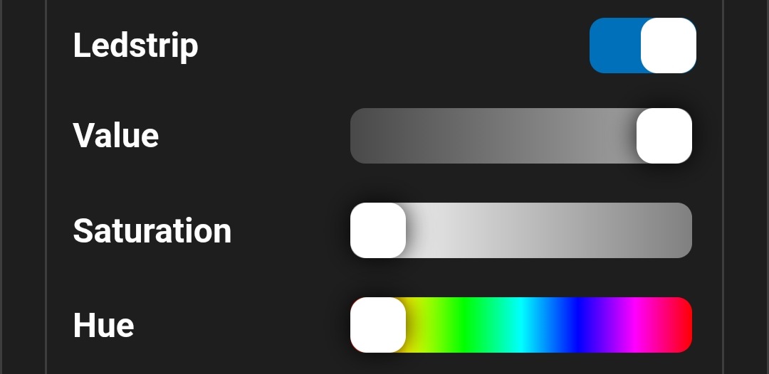
Binaire uitgangen, zoals relais of digitale uitgangen, hebben enkel een aan/uit-bedieningselement. Niet-binaire uitgangen hebben bovenop aan/uit ook een instelbare waarde (Value). Daarmee stel je onder meer de dimwaarde van verlichting of de positie van een rolluik in. Voor multi-color verlichting zijn er bovendien nog extra bedieningselementen om de kleur en verzadiging in te stellen.
Binary outputs, such as relays or digital outputs, only have an on/off control. Non-binary outputs have an adjustable value (Value) in addition to on/off. This lets you set, for example, the dim level of lighting or the position of a shutter. For multi-color lighting there are additional controls to set color and saturation.
- LumaLink‑busadres van de module
- Bediening van binaire uitgang (enkel aan/uit)
- In dit voorbeeld: een relaisuitgang
- Bediening van niet‑binaire uitgang (aan/uit + waarde)
- In dit voorbeeld: een rolluik
- Value — positie rolluik — rechts is open
- Bediening van niet‑binaire uitgang (aan/uit + waarde)
- In dit voorbeeld: een 0-10V dimmer
- Value — dimwaarde — rechts = maximale helderheid
- Bediening van niet‑binaire multi‑coloruitgang (aan/uit, waarde, verzadiging en kleur)
- In dit voorbeeld: een 24V‑ledstrip op CH6-CH8
- Value — dimwaarde — rechts = maximale helderheid
- Saturation — kleurverzadiging — rechts = maximale kleur
- Hue — kleurinstelling
- Status van binaire sensor (ingang met enkel aan/uit)
- Status van drukknopingang (ingang met enkel aan/uit)
- Status van niet‑binaire sensor (ingang met alleen een waarde)
- In dit voorbeeld: 0-10V ingang
- Status van ingangen op LumaSense‑drukknopinterface
- CH101‑LMS Switch‑1.2 — LumaLink‑kanaal 101, 2e drukknop op interface met LumaSense‑adres 01
- Drukknoppen die nog nooit werden ingedrukt, zijn hier verborgen
- Wisselen tussen weergave van ingangen of uitgangen
- Module‑configuratie openen
- LumaLink bus address of the module
- Control of a binary output (on/off only)
- In this example: a relay output
- Control of a non-binary output (on/off + value)
- In this example: a shutter
- Value — shutter position — right is open
- Control of a non-binary output (on/off + value)
- In this example: a 0-10V dimmer
- Value — dim level — right = maximum brightness
- Control of a non-binary multi-color output (on/off, value, saturation and color)
- In this example: a 24V LED strip on CH6-CH8
- Value — dim level — right = maximum brightness
- Saturation — color saturation — right = maximum color
- Hue — color setting
- Status of a binary sensor (input with on/off only)
- Status of a push-button input (input with on/off only)
- Status of a non-binary sensor (input with value only)
- In this example: a 0-10V input
- Status of inputs on a LumaSense push-button interface
- CH101‑LMS Switch‑1.2 — LumaLink channel 101, 2nd button on interface with LumaSense address 01
- Buttons that have never been pressed are hidden here
- Switch between the inputs and outputs view
- Open module configuration
Quick start
Snelle start
This section provides practical examples for configuring common use cases. The examples assume the module is already connected and accessible via LumaConfig.
Deze sectie bevat praktische voorbeelden voor veelvoorkomende configuraties. De voorbeelden gaan ervan uit dat de module al verbonden is en toegankelijk is via LumaConfig.
Relay outputs
Relaisuitgangen
Relay outputs can be configured to switch lighting circuits or other loads.
De relaisuitgangen kunnen geconfigureerd worden om lichtpunten of andere belastingen te schakelen.
- Connect the load/lighting to the module as described in the technical manual.
- Sluit de belasting/verlichting aan op de module zoals beschreven in de technische handleiding.
-
In the LumaConfig dashboard, go to
Configuration → Channel Configuration → Desired relay channel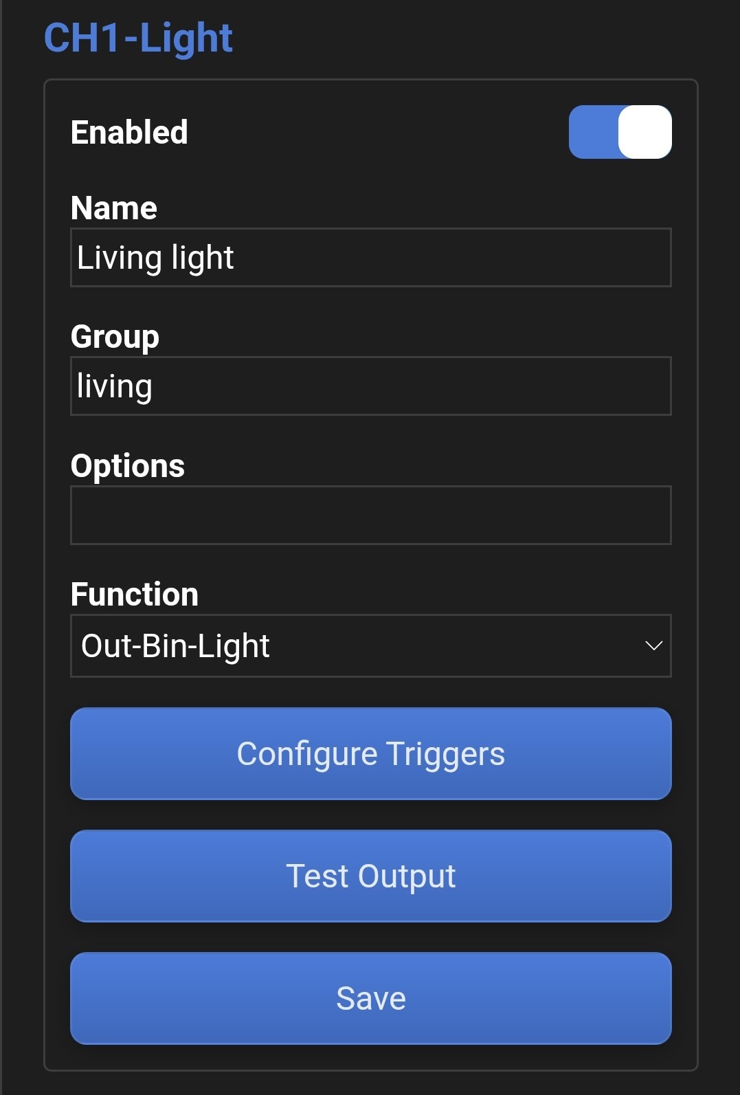
-
In LumaConfig dashboard, ga naar
Configuration → Channel Configuration → Gewenste relais kanaal - {{GLOBAL_QS_NAME_EN}}
- {{GLOBAL_QS_NAME_NL}}
- {{GLOBAL_QS_GROUP_EN}}
- {{GLOBAL_QS_GROUP_NL}}
-
The
Lightfunction is the default and in most cases the recommended function (switching lighting circuits). There is also aGenericfunction that can be used for other types of loads. In practice, both functions behave the same and "Light" will also work for switching, for example, an external relay. One key difference is that the "Light" function responds to the "all on" and "all off" commands, while the "Generic" function does not. This behavior can be changed using channel optionsIGAONandIGAOFF. -
De functie
Lightis de standaard functie en in de meeste gevallen ook de gewenste functie (schakelen lichtpunten). Verder is er ook nog een functieGenericdie gebruikt kan worden voor andere types belastingen. In essentie zijn beide functies identiek en zal de functie "Light" ook gewoon werken voor het schakelen van bijvoorbeeld een extern relais. Een belangrijk verschil is wel dat de "Light" functie reageert op een "alles aan" en "alles uit", de "Generic" functie niet. Dit gedrag kan trouwens wel aangepast worden met kanaaloptiesIGAONenIGAOFF. - {{GLOBAL_QS_RESTART_EN}}
- {{GLOBAL_QS_RESTART_NL}}
- {{GLOBAL_QS_TRIGGERS_EN}}
- {{GLOBAL_QS_TRIGGERS_NL}}
Dimmers
Dimmers
Flex IO channels (CH6-CH9) can be used as 0-10 V control outputs for external dimmers or as direct PWM dimmers (12-24 V).
FIO-kanalen (CH6-CH9) kunnen worden gebruikt als 0-10 V-stuuruitgang voor externe dimmers of als directe PWM-dimmer (12-24V).
- Connect the external 0-10V dimmer or LED lighting to the module as described in the technical manual.
- Sluit de externe 0-10V dimmer of ledverlichting aan op de module zoals beschreven in de technische handleiding.
-
In the LumaConfig dashboard, go to
Configuration → Channel Configuration → Desired Flex IO channel (CH6-CH9)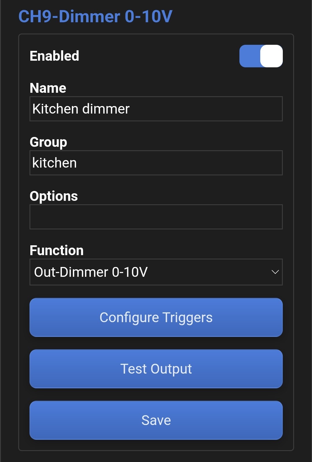
-
In LumaConfig dashboard, ga naar
Configuration → Channel Configuration → Gewenste Flex IO kanaal (CH6-CH9) - {{GLOBAL_QS_NAME_EN}}
- {{GLOBAL_QS_NAME_NL}}
- {{GLOBAL_QS_GROUP_EN}}
- {{GLOBAL_QS_GROUP_NL}}
-
Set the channel function to
Dimmer (PWM)orDimmer 0-10V. Flex IO channels can automatically detect connected LED(strips), which may cause the function to switch automatically between Dimmer and Dimmer 0-10V. If this detection is not correct, use channel optionPWM10Vto force the output in PWM mode or 0-10V mode. -
Pas de functie van de uitgang aan naar
Dimmer (PWM)ofDimmer 0-10V. FIO-kanalen zijn in staat om verbonden ledstrips automatisch te detecteren, dat kan ervoor zorgen dat de functie automatisch gewijzigd wordt tussen Dimmer en Dimmer 0-10V. Indien deze detectie niet correct werkt, kan kanaaloptiePWM10Vgebruikt worden om de uitgang te forceren in PWM- of 0-10V modus. - {{GLOBAL_QS_RESTART_EN}}
- {{GLOBAL_QS_RESTART_NL}}
- {{GLOBAL_QS_TRIGGERS_EN}}
- {{GLOBAL_QS_TRIGGERS_NL}}
Flex IO channels
Flex IO kanalen
Flex IO channels (CH6-CH9) support many functions such as dimming, digital inputs/outputs, analog inputs/outputs, pulse counters, and more. In the example below, a Flex IO channel is configured as an S0 pulse counter input for kWh measurement. An overview of the possible channel functions can be found in Channel function overview.
FIO-kanalen (CH6-CH9) kunnen veel functies vervullen, zoals dimmen, digitale in- en uitgangen, analoge in- en uitgangen, pulstellers, enzovoort. In het voorbeeld hieronder configureren we een FIO-kanaal als S0-pulsteller-ingang voor kWh-meting. Een overzicht van de mogelijke functies met extra informatie kan je vinden in Overzicht kanaalfuncties.
- Connect the pulse output of the energy meter to the module as described in the technical manual.
- Sluit de pulsuitgang van de energiemeter aan op de module zoals beschreven in de technische handleiding.
-
In the LumaConfig dashboard, go to
Configuration → Channel Configuration → Desired Flex IO channel.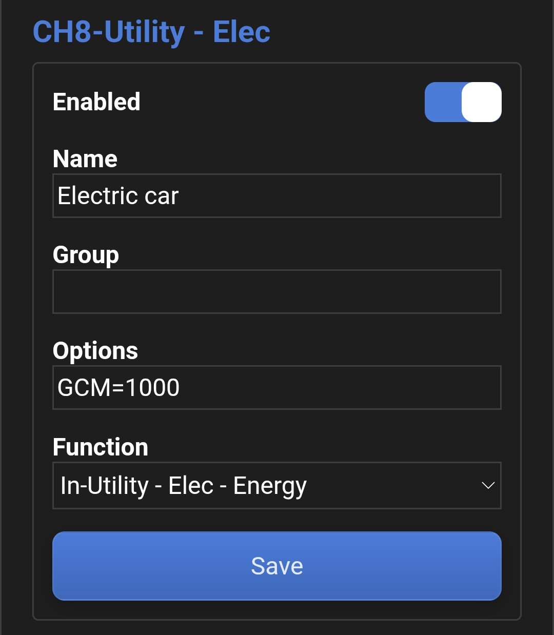
-
In LumaConfig dashboard, ga naar
Configuration → Channel Configuration → Gewenste Flex IO kanaal. - Preferably set a name to make the input easier to identify.
- Stel bij voorkeur een naam in om de ingang makkelijker te identificeren.
-
Set the channel function to
In-Utility-Elec-Energy. In-Pulse-Count is also an option, but it only counts pulses without automatic conversion to kWh. -
Pas de functie van de uitgang aan naar
In-Utility-Elec-Energy. In-Pulse-Count is ook een optie, maar deze functie houdt enkel het aantal pulsen bij zonder automatische omzetting naar kWh. -
Configure the correct pulse/kWh conversion. By default, 1000 pulses per kWh is assumed (= 1 pulse per Wh).
If your meter uses a different value, use channel option GCM. In the example, the meter outputs 100 pulses per kWh,
setting
GCM=1000applies a factor x10. GCM=10000 applies a factor x100, GCM=10 applies a factor x0.1 etc. -
Stel de juiste puls/kWh conversie in, standaard wordt uitgegaan van 1000 pulsen per kWh (= 1 puls per Wh).
Als jouw energiemeter een andere conversie gebruikt, heb je kanaaloptie GCM nodig.
De energiemeter in ons voorbeeld geeft 100 pulsen per kWh,
GCM=1000zorgt voor een factor x10. GCM=10000 geeft factor x100, GCM=10 geeft factor x0,1 etc. -
If you want to include previous energy consumption, you can set a start value using option GCSC.
For example,
GCSC=12000starts at 12 kWh and continues counting from there. -
Indien er in het verleden al energieverbruik is geweest dat je wil meenemen, kan je een startwaarde configureren met optie GCSC.
Optie
GCSC=12000zal bijvoorbeeld starten bij 12kWh en vanaf daar verder tellen. -
Restart the module if the background turns orange to apply all changed settings.
After restarting, you can view the energy meter in the Dashboard. Note that besides the kWh counter there is also a Rate element.
This Rate value is a power estimate based on the time between pulses,
this is not very accurate when the time between pulses is large.

-
Herstart de module indien de achtergrond oranje kleurt om alle gewijzigde instellingen toe te passen.
Na het herstarten kan je de energiemeter bekijken in het Dashboard.
Merk ook op dat er buiten de kWh teller ook steeds een Rate element zichtbaar is.
Dit Rate element is een vermogenschatting op basis van de tijd tussen de pulsen, dit is niet super nauwkeurig
wanneer de tijd tussen de pulsen groot is.
DMX512 fixtures
DMX512 armaturen
DMX512 is a standardized protocol to control dimmable lighting fixtures and LED drivers. Luma One modules can control up to 12 DMX channels. These channels behave like regular outputs, with support for triggers, groups, scenes, learning mode, etc.
DMX512 is een gestandaardiseerd protocol om dimbare verlichting zoals armaturen en LED drivers aan te sturen. Luma One-modules kunnen tot 12 DMX-kanalen aansturen. Deze kanalen zijn op dezelfde manier te gebruiken als de vaste uitgangen op de module (met ondersteuning voor triggers, groepen, sferen, leermodus, etc.).
- Connect the DMX512 fixtures to the RS485 port of the module as described in the technical manual.
- Sluit de DMX512 armaturen aan op de RS485-poort van module zoals beschreven in de technische handleiding.
- In the LumaConfig dashboard, go to
Configuration → Module Configuration → DMXand enable DMX512 master mode. Save the settings and restart the module.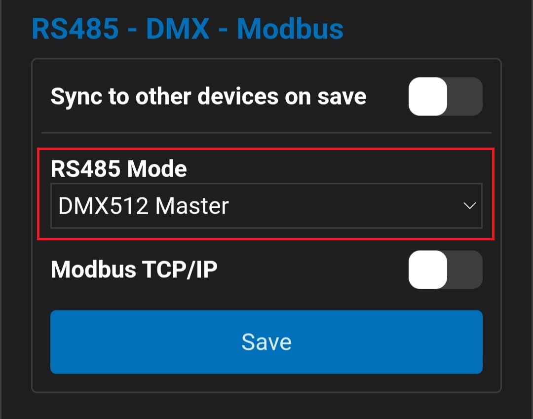
-
In LumaConfig dashboard, ga naar
Configuration → Module Configuration → DMXen activeer de DMX512 master mode. Sla de instellingen op en herstart vervolgens de module. -
In the LumaConfig dashboard, go to
Configuration → Channel Configuration → Desired DMX channel.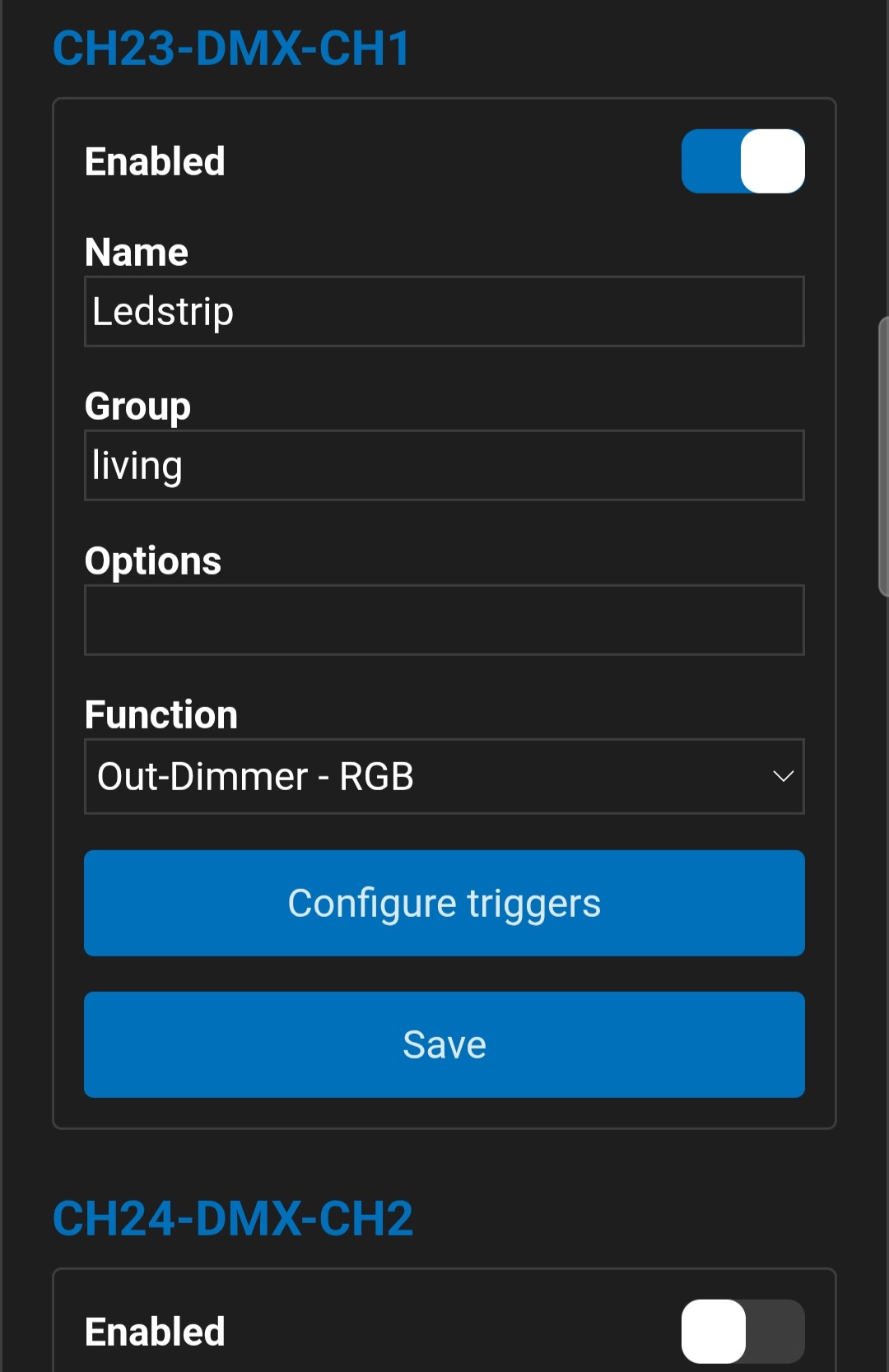
-
In LumaConfig dashboard, ga naar
Configuration → Channel Configuration → Gewenste DMX-kanaal. - {{GLOBAL_QS_NAME_EN}}
- {{GLOBAL_QS_NAME_NL}}
- {{GLOBAL_QS_GROUP_EN}}
- {{GLOBAL_QS_GROUP_NL}}
-
Set the channel function to
Dimmer(1 DMX channel),Dimmer - CT(2 DMX channels) orDimmer RGB(W)(4 DMX channels). In this example we use an RGB LED strip. Not all multi-color functions are available on all DMX channels, see the DMX512 mapping for details. -
Pas de functie van de uitgang aan naar
Dimmer(1 DMX-kanaal),Dimmer - CT(2 DMX-kanalen) ofDimmer RGB(W)(4 DMX-kanalen). In dit voorbeeld werken we met een RGB ledstrip. Niet alle multi-color functies zijn beschikbaar op alle 10 DMX-kanalen, bekijk de DMX512 mapping voor meer info. - {{GLOBAL_QS_RESTART_EN}}
- {{GLOBAL_QS_RESTART_NL}}
- If the fixtures do not work correctly, check the following:
- Do the module DMX channels match the fixture’s DMX mapping/addressing?
- Is a 120 Ω termination resistor installed near the last fixture on the RS485/DMX bus?
- Is the data signal polarity correct and is GND connected? Try swapping A and B.
-
Indien de armaturen niet functioneren, bekijk dan zeker het volgende:
- Komen de DMX-kanalen van de module overeen met de DMX mapping van het armatuur?
Controleer module DMX mapping hier. - 120 Ohm terminatieweerstand geïnstalleerd nabij het laatste armatuur op de RS485/DMX-bus?
- Polariteit van datasignaal correct en GND verbonden? Probeer A en B datasignaal om te wisselen.
- Komen de DMX-kanalen van de module overeen met de DMX mapping van het armatuur?
- {{GLOBAL_QS_TRIGGERS_EN}}
- {{GLOBAL_QS_TRIGGERS_NL}}
Shutters or screens
Rolluiken of screens
Relay outputs can also be configured to control shutter or screen motors. Relays work in pairs (up and down). With 16 relays you can control up to 8 motors.
Relaisuitgangen kunnen ook geconfigureerd worden om screen- of rolluikmotoren aan te sturen. Relais gaan dan steeds in paren werken (omhoog en omlaag). Met 16 relais kan je zo 8 motoren aansturen.
- Connect the motor to the module as described in the technical manual.
- Sluit de motor aan op de module zoals beschreven in de technische handleiding.
-
In the LumaConfig dashboard, go to
Configuration → Channel Configuration → Desired relay channel. Only the odd-numbered (open) channels can be configured, the even-numbered (close) channels are configured automatically.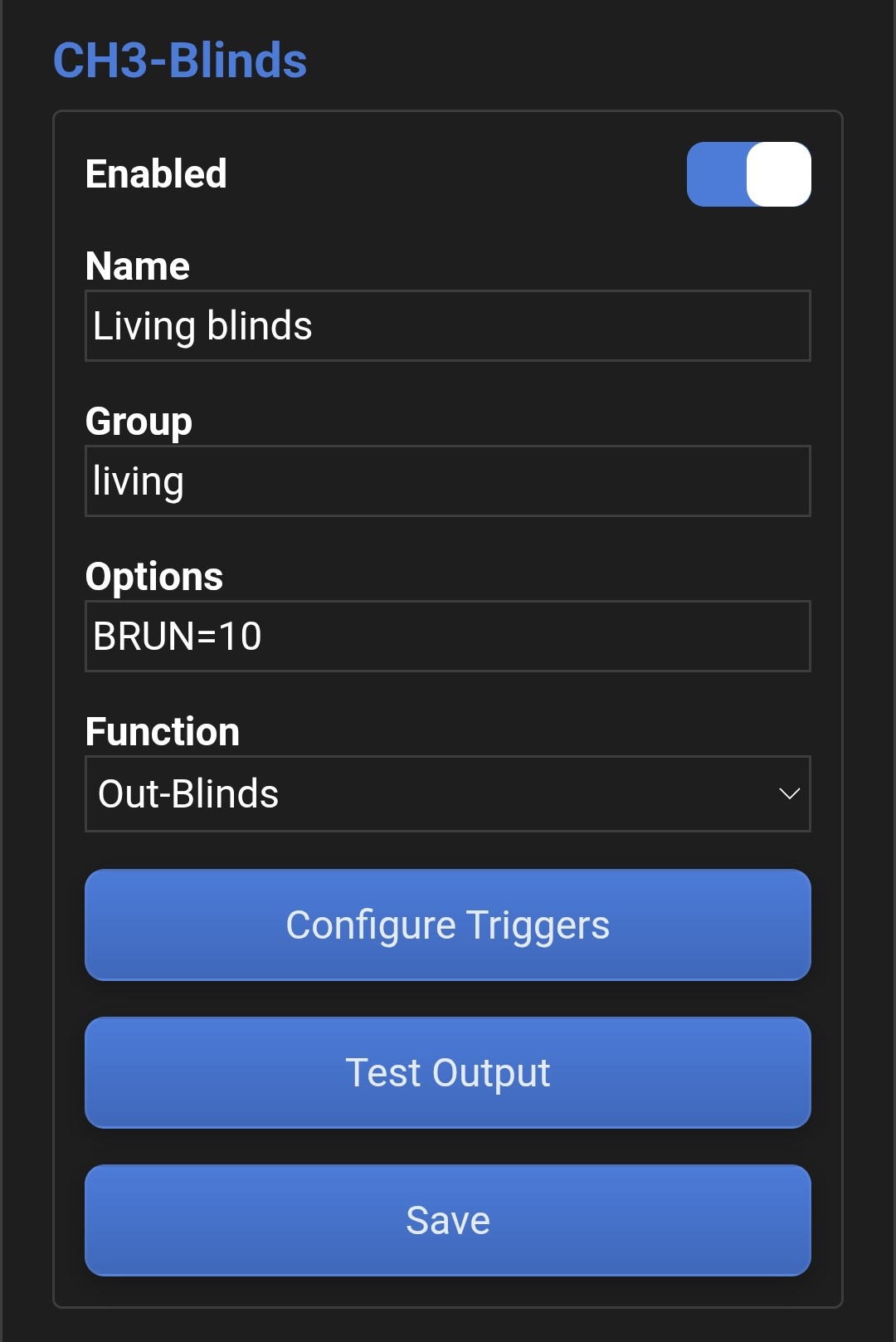
-
In LumaConfig dashboard, ga naar
Configuration → Channel Configuration → Gewenste relais kanaal. Enkel de oneven (openen) kanalen kunnen geconfigureerd worden, de even kanalen (sluiten) worden automatisch mee geconfigureerd. - {{GLOBAL_QS_NAME_EN}}
- {{GLOBAL_QS_NAME_NL}}
- {{GLOBAL_QS_GROUP_EN}}
- {{GLOBAL_QS_GROUP_NL}}
- Set the channel function to Out-Blinds.
- Pas de functie van de uitgang aan naar Out-Blinds.
-
Set the motor run time using the
BRUNchanneloption. "BRUN=10" corresponds to a run time of 10 seconds.- No additional margin is required, as an extra margin of 20% is already applied when fully opening or closing.
- The run time can also be learned automatically when push-buttons are linked using learning mode.
-
Stel de looptijd van de motor in met de BRUN kanaaloptie. BRUN=10 komt overeen met een looptijd van 10 seconden.
- Er is geen extra marge op de looptijd nodig aangezien er al een extra marge wordt toegepast van 20% bij het volledig openen/sluiten.
- De looptijd kan ook automatisch worden aangeleerd indien drukknoppen met de leermodus gekoppeld worden.
- {{GLOBAL_QS_RESTART_EN}}
- {{GLOBAL_QS_RESTART_NL}}
- {{GLOBAL_QS_TRIGGERS_EN}}
- {{GLOBAL_QS_TRIGGERS_NL}}
LumaSense push-button interfaces
LumaSense drukknopinterfaces
The LumaSense bus can be used to expand the module with additional push-button inputs. For this, LumaSense push-button interfaces are required.
De LumaSense-bus kan gebruikt worden om de module uit te breiden met extra drukknopingangen, hiervoor heb je LumaSense-drukknopinterfaces nodig.
- Connect the LumaSense push-button interfaces to the module (CH10) as described in the technical manual.
- Sluit de LumaSense-drukknopinterfaces aan op de module (CH10) zoals beschreven in de technische handleiding.
- Ensure that each push-button interface on the LumaSense bus has a unique address between 1 and 19. The Luma One (XL) module itself does not have a LumaSense bus address.
- Zorg ervoor dat elke drukknopinterface op de LumaSense-bus een uniek adres heeft tussen 1 en 19. De Luma One (XL) module zelf heeft geen LumaSense-busadres.
- Restart the module. During startup, the LumaSense push-button interfaces are detected automatically. To prevent unused push-button inputs from being detected as well, the inputs must be activated once. Do this by pressing each push-button that you actually intend to use once (you do this automatically if you use the learning mode).
- Herstart de module, bij het opstarten worden de LumaSense-drukknopinterfaces automatisch gedetecteerd. Om te voorkomen dat er ook veel niet-gebruikte drukknopingangen gedetecteerd worden, moeten de drukknopingangen eenmalig geactiveerd worden. Dit doe je door de drukknoppen die je daadwerkelijk gaat gebruiken 1x in te drukken (dit doe je automatisch als je de leermodus gebruikt).
-
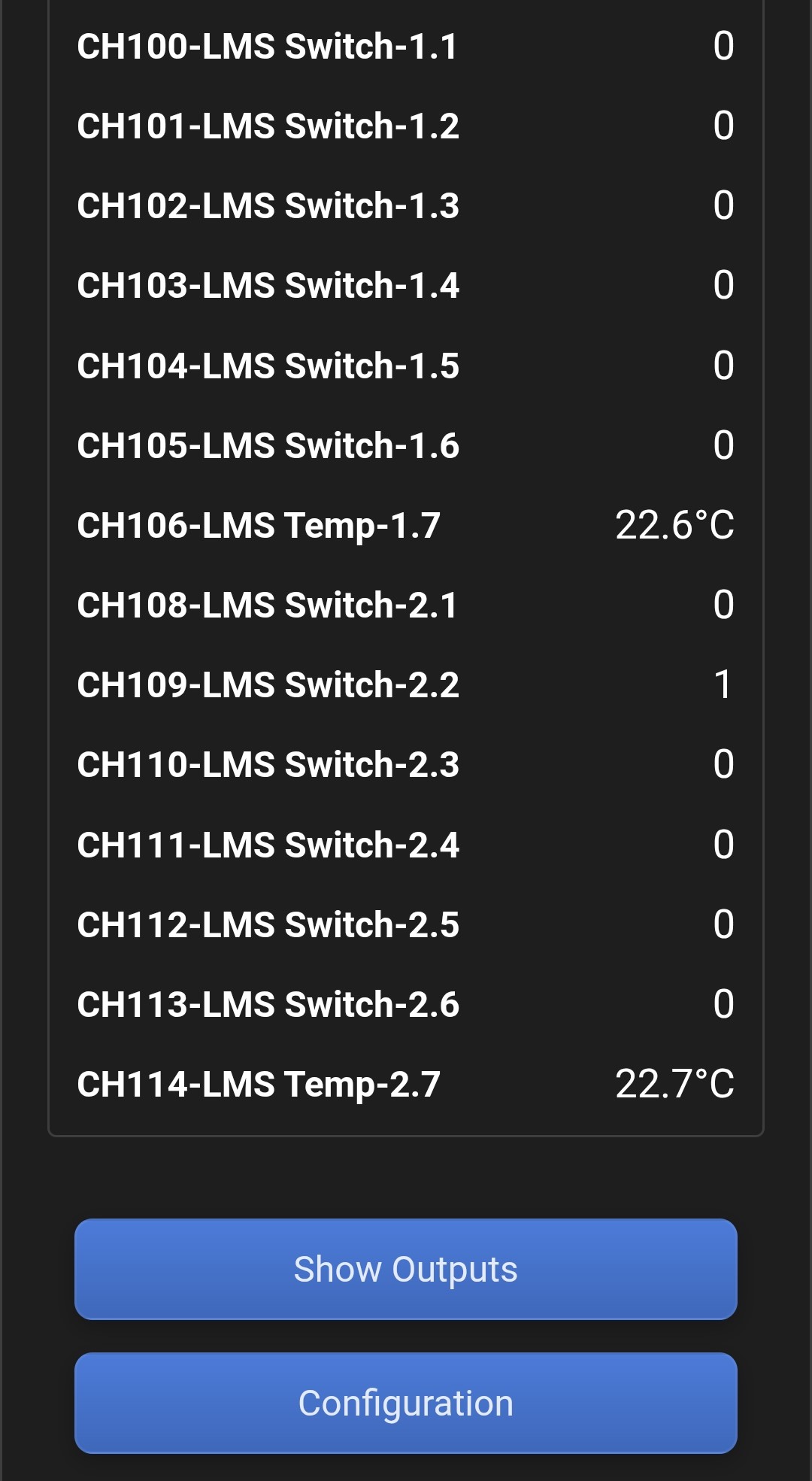
The push-button interfaces are now visible in the Dashboard. In this example, two push-button interfaces are present
with LumaSense addresses 1 and 2.
The inputs of the push-button interfaces are mapped to LumaLink channels 100 through 114.
The Dashboard refreshes the input status every 2 seconds,
so you need to press the buttons long enough to see the status change.
-
De drukknopinterfaces zijn nu zichtbaar in het dashboard. In dit geval hebben we 2 drukknopinterfaces op LumaSense adres 1 en 2.
Verder zien we ook dat de ingangen op de drukknopinterfaces gemapped worden naar LumaLink-kanalen 100 tot 114.
Het dashboard ververst de status van de ingangen elke 2 seconden,
je moet dus lang genoeg drukken om de status van de drukknoppen te zien veranderen.
- Interfaces that are no longer in use (or whose address has been changed) are only removed from the input list after a module restart. If inputs are missing from the list, try reloading the page.
- Interfaces die niet meer in gebruik zijn (of waarbij het adres is gewijzigd), worden pas verwijderd uit de lijst met ingangen na een herstart van de module. Missen er ingangen in de lijst, probeer dan de pagina te herladen.
Module settings
Module-instellingen
Network settings
Netwerkinstellingen
A network connection is required when using Modbus TCP/IP, MQTT (LumaConnect, Home Assistant, etc.) or time-based triggers. Even if you do not use these features, it is recommended to connect the module to the home network. This ensures that LumaConfig remains accessible without having to put the module into AP mode every time.
Een netwerkverbinding is noodzakelijk als je gebruikmaakt van Modbus TCP/IP, MQTT (LumaConnect, Home Assistant,..) of tijdgebaseerde triggers. Ook als je deze features niet gebruikt, is het verstandig de module met het thuisnetwerk te verbinden. Zo blijft LumaConfig beschikbaar zonder de module telkens in AP-modus te zetten.
If the module is controlled directly via its IP address (e.g. Modbus TCP/IP), it is recommended to use a static IP address to prevent the DHCP address assigned by the router from changing. Make sure that the chosen static IP address does not conflict with the router's DHCP address range. If necessary, consult the router settings or documentation.
Wordt de module rechtstreeks via het IP-adres aangestuurd (bijv. Modbus TCP/IP), kies dan bij voorkeur een statisch IP-adres om te voorkomen dat het door de router toegewezen DHCP-adres wijzigt. Let erop dat het gekozen vast IP-adres niet conflicteert met het DHCP-adresbereik van je router, raadpleeg zo nodig de routerinstellingen of handleiding.
| Setting | Dashboard → Configuration → Module settings | Instelling | Dashboard → Configuration → Module settings |
|---|---|---|---|
| Network Method | Network method
|
Network Method | Netwerkmethode
|
| Wi-Fi SSID | Wi-Fi network name | Wi-Fi SSID | Naam van Wi-Fi-netwerk |
| Wi-Fi Password | Wi-Fi network password | Wi-Fi Password | Wachtwoord van Wi-Fi-netwerk |
| Static IPv4 Address | Static IPv4 address
|
Static IPv4 Address | Statisch IPv4-adres
|
| Static IPv4 Mask | Static IPv4 subnet mask
|
Static IPv4 Mask | Statisch IPv4-netmasker
|
| Static IPv4 Gateway | Static IPv4 gateway
|
Static IPv4 Gateway | Statische IPv4-gateway
|
| Preview | Weergave | 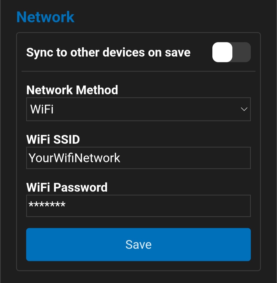 |
LumaLink bus
LumaLink-bus
To allow modules to communicate with each other, LumaLink must be enabled and a unique LumaLink bus address greater than 0 must be configured.
Om communicatie tussen modules mogelijk te maken, moet LumaLink ingeschakeld zijn en moet er een uniek LumaLink-busadres groter dan 0 ingesteld worden.
If modules cannot be connected via the wired LumaLink bus for any reason, a LumaLink connection can be established over MQTT (network). However, this is strongly discouraged, as we have no control over the intermediate network equipment.
Kunnen modules om welke reden dan ook niet via de bekabelde LumaLink met elkaar verbonden worden, dan kun je een LumaLink-verbinding opzetten over MQTT (netwerk). We raden we dit echter sterk af omdat we geen controle hebben over de tussenliggende netwerkapparatuur.
| Setting | Dashboard → Configuration → Module settings | Instelling | Dashboard → Configuration → Module settings |
|---|---|---|---|
| LumaLink mode |
LumaLink mode
|
LumaLink Mode |
LumaLink modus
|
| Bus address |
Unique LumaLink bus address
|
Bus address |
Uniek LumaLink-busadres
|
| Preview | Weergave | 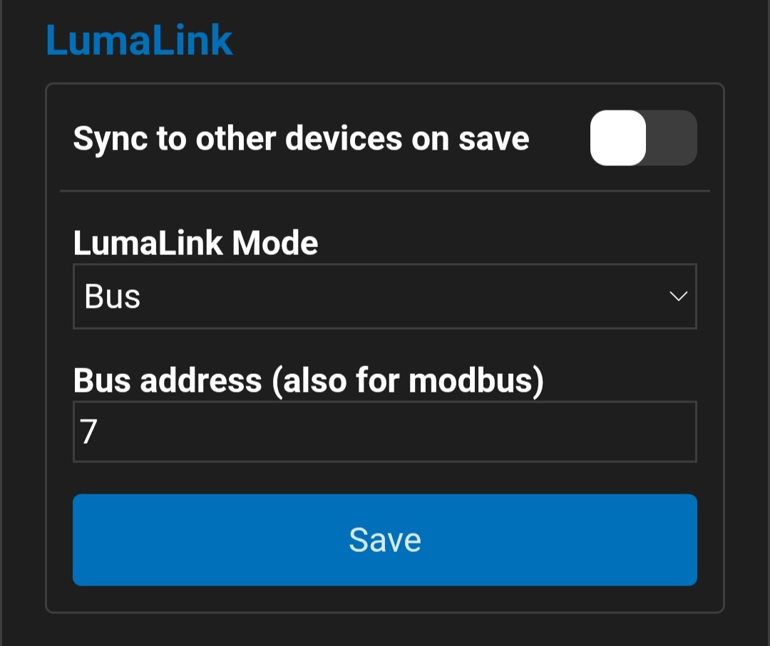 |
MQTT
MQTT
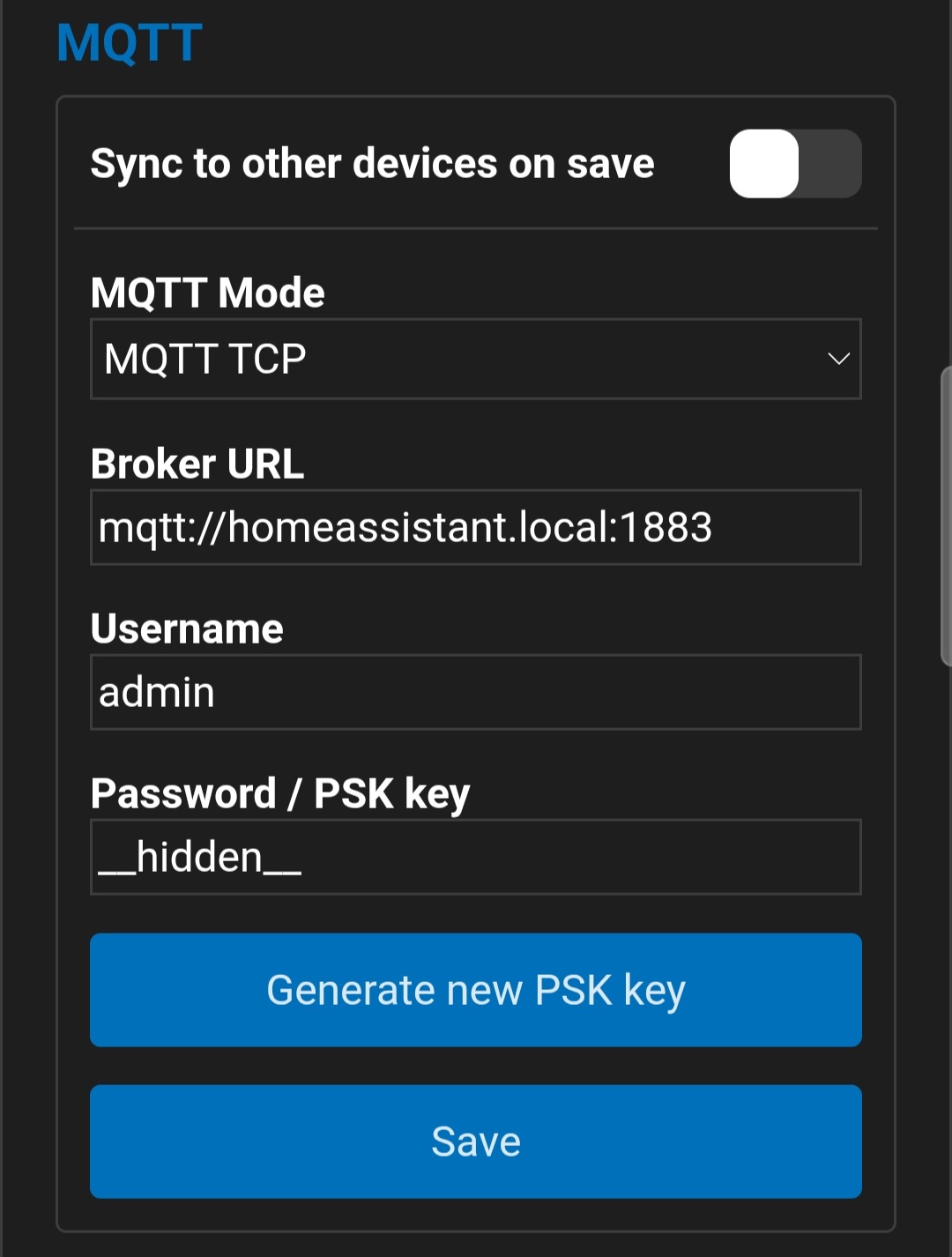
Two MQTT variants are currently supported: MQTT TCP and MQTT SSL PSK.
MQTT TCP is the simplest and fastest option. Although authentication requires a username and password,
data exchanged between the broker and the module is not encrypted, which is a potential security risk.
Er worden momenteel twee MQTT-varianten ondersteund, MQTT TCP en MQTT SSL PSK.
MQTT TCP is de eenvoudigste en snelste variant. Hoewel de aanmeldprocedure een gebruikersnaam en wachtwoord vereist,
wordt de data tussen de broker en de module niet versleuteld, dit is een potentieel beveiligingsrisico.
MQTT SSL PSK uses data encryption based on a pre-shared key (PSK). This method is currently not widely supported by MQTT brokers, but it does work with Mosquitto MQTT, for example (Home Assistant). To ensure robust encryption, the PSK key must have a fixed length and should preferably be random; therefore, a random PSK key generator is provided.
MQTT SSL PSK maakt wel gebruik van data-versleuteling op basis van een PSK-sleutel. Deze methode wordt momenteel nog niet breed ondersteund door MQTT-brokers, maar met Mosquitto MQTT werkt dit bijvoorbeeld wel (Home Assistant). Om een robuuste versleuteling te garanderen, moet de PSK-sleutel een vaste lengte hebben en is deze bij voorkeur willekeurig, daarom is er ook een random PSK-sleutelgenerator voorzien.
| Setting Instelling | Dashboard → Configuration → Module settings Dashboard → Configuration → Module settings |
|---|---|
| MQTT mode |
MQTT mode
MQTT-modus
|
| Broker URL |
MQTT broker URL, including port
URL van de MQTT-broker, inclusief poort
|
| Username | MQTT username MQTT-gebruikersnaam |
| Password / PSK key | MQTT password, or PSK key when using MQTT SSL PSK. MQTT-wachtwoord, of PSK-sleutel bij gebruik van MQTT SSL PSK. |
| Preview Weergave |
|
Location and time
Locatie en tijd
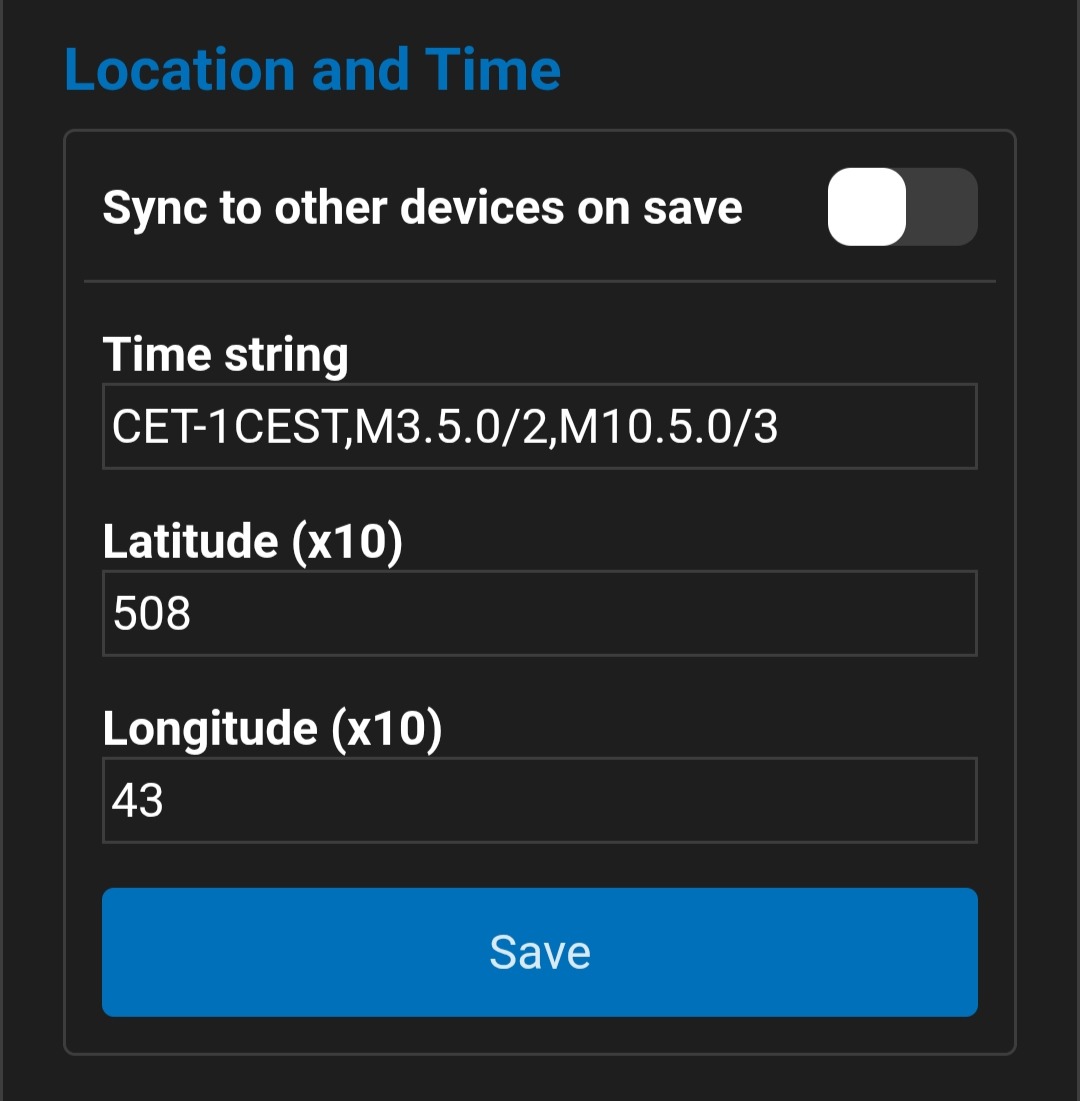
Modules keep their internal clock up to date using the SNTP protocol. When using time-based triggers or the astronomical clock (sunrise and sunset), it is important that the time and location settings are configured correctly. The POSIX-TZ time string also defines the daylight saving time.
Modules houden hun interne klok up-to-date met behulp van het SNTP-protocol. Wanneer je tijdgebaseerde triggers of de astroklok (zonsopgang en zonsondergang) gebruikt, is het belangrijk dat tijd- en locatie-instellingen correct zijn. In de POSIX-TZ-tijdstring is ook de zomer- en wintertijd omschakeling gedefinieerd.
| Setting Instelling | Dashboard → Configuration → Module settings Dashboard → Configuration → Module settings |
|---|---|
| Time string |
POSIX-TZ time string
Tijdstring in POSIX-TZ formaat
|
| Latitude |
Latitude for astronomical clock
Breedtegraad voor astroklok
|
| Longitude |
Longitude for astronomical clock
Lengtegraad voor astroklok
|
| Preview Weergave |
|
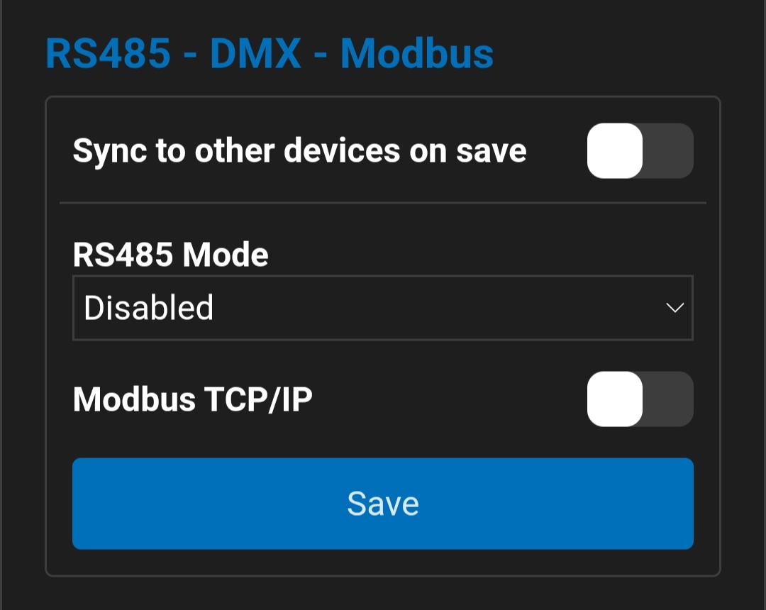
RS485 — DMX — Modbus
RS485 — DMX — Modbus
The RS485 port can be used in several ways. For example, it can be used to control the module via DMX512 or Modbus RTU (module as slave). The reverse is also possible: configure the RS485 port as a DMX512 master, allowing the module to control external DMX512 fixtures (such as LED lighting, up to a maximum of 10 channels).
De RS485-poort kan op verschillende manieren gebruikt worden. Bijvoorbeeld om de module aan te sturen via DMX512 of Modbus RTU (module als slave). Ook het omgekeerde is mogelijk: stel de RS485-poort in als DMX512-master en de module kan zo externe DMX512 armaturen aansturen (zoals ledverlichting, max. 10 kanalen).
| Setting Instelling | Dashboard → Configuration → Module settings Dashboard → Configuration → Module settings |
|---|---|
| RS485 mode RS485-modus |
RS485 mode
RS485-modus
|
| Modbus TCP/IP | Enable Modbus TCP/IP Modbus TCP/IP inschakelen (*1) |
| Preview Weergave |
|
Other
Overig
Various additional module settings.
Diverse aanvullende module-instellingen.
| Setting Instelling | Dashboard → Configuration → Module settings Dashboard → Configuration → Module settings |
|---|---|
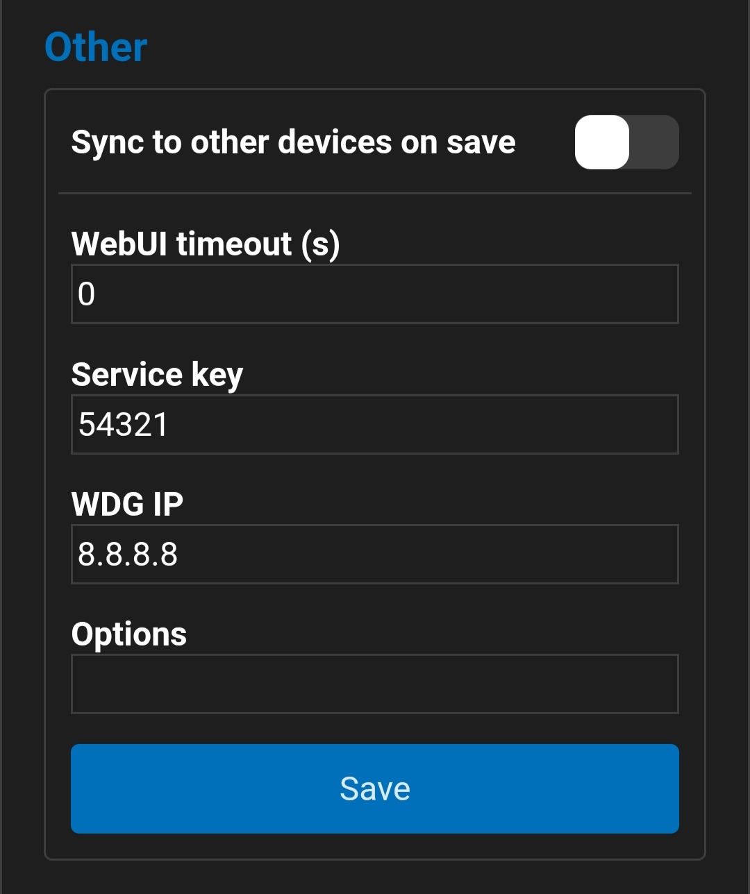
| LumaConfig timeout |
LumaConfig is disabled after this period, in seconds.
LumaConfig wordt uitgeschakeld na deze periode, in seconden.
|
| Service key |
Service key for access to settings
Service key voor toegang tot instellingen
|
| WDG IP | Network watchdog IP address Network watchdog IP-adres |
| Options | Advanced module settings Geavanceerde module-instellingen |
| Preview Weergave |
|
Firmware update and backup
Firmware update en backup
| Setting Instelling | |
|---|---|
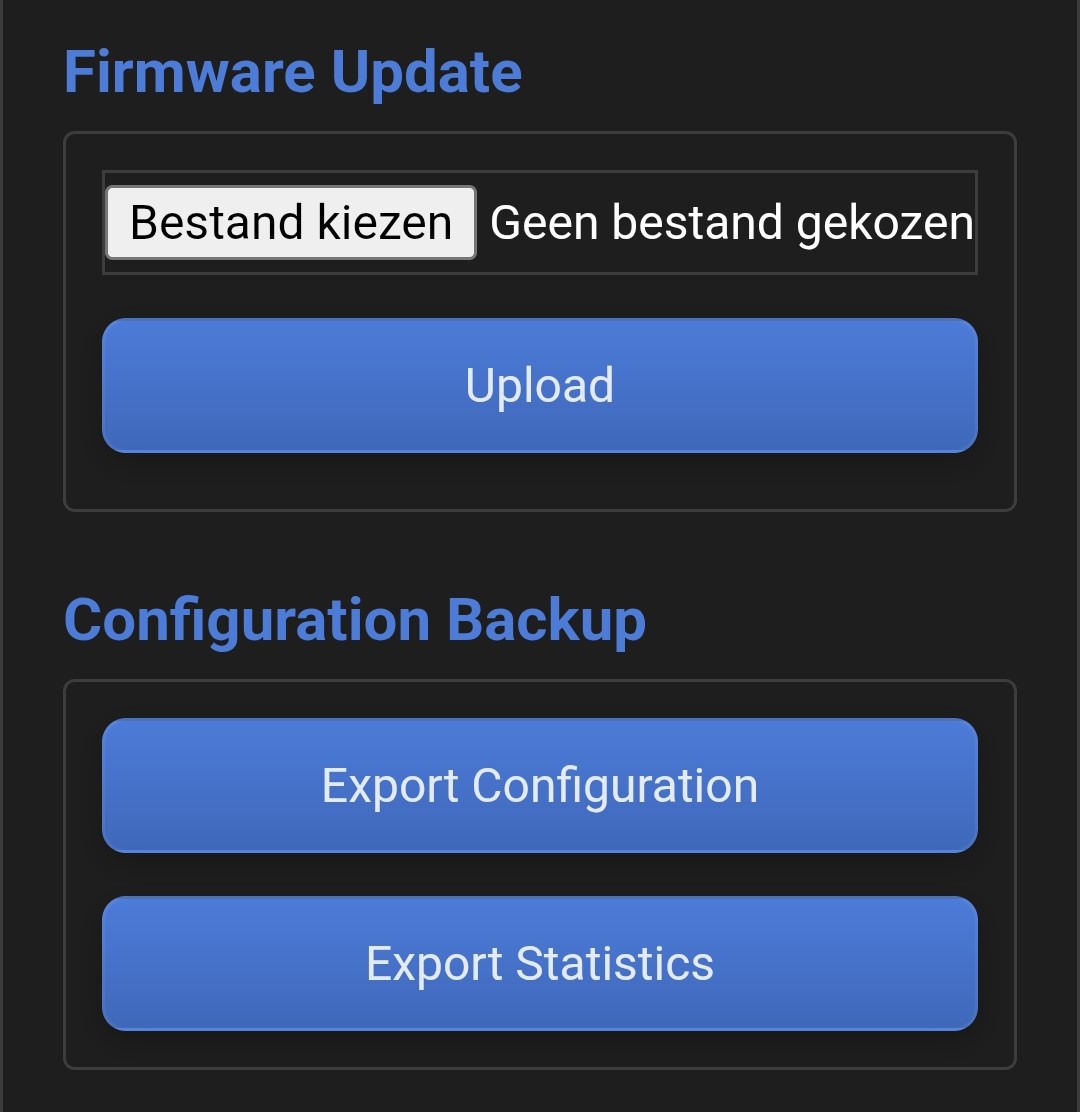
| Choose file Bestand kiezen |
Select new module firmware.
Selecteer nieuwe module firmware.
|
| Upload |
Upload the selected firmware to the module.
Upload de geselecteerde firmware naar de module.
|
| Export configuration Export configuratie |
Export the complete module configuration to a ".nlcmc" file.
Exporteer de volledige moduleconfiguratie naar een ".nlcmc"-bestand.
|
| Export statistics Export statistieken | Export statistical data related to module lifetime and reliability. Exporteer statistische gegevens met betrekking tot de levensduur en betrouwbaarheid van de module. |
| Preview Weergave |
|
Configure Inputs and Outputs
In- en uitgangen configureren
Inputs and outputs (= channels) can easily be configured with LumaConfig. For outputs, you can also program triggers (e.g., linking push-buttons). Outputs can always be configured, inputs not always. Push-button inputs for example, have no configuration.
In- en uitgangen (= kanalen) kunnen eenvoudig met LumaConfig geconfigureerd worden. Voor uitgangen kunnen er ook steeds triggers geprogrammeerd worden (bv koppelen van drukknoppen). Uitgangen zijn altijd te configureren, ingangen niet altijd, drukknop-ingangen hebben bijvoorbeeld geen configuratie.
General Channel Settings
Algemene kanaalinstellingen
| Instelling | Dashboard → Configuration → Channel Configuration | Dashboard → Configuration → Channel Configuration |
|---|---|---|
| Enabled | Channel enabled (does not switch the output on or off) | Kanaal in gebruik (niet voor in/uitschakelen van de uitgang) |
| Name | Optional name for the output | Optionele naam voor uitgang |
| Group |
Optional group name for the output
|
Optionele groepsnaam voor uitgang
|
| Options |
Advanced channel options
|
Geavanceerde kanaalopties
|
| Function |
Output function
|
Functie van de uitgang
|
| Configure triggers |
Configure triggers and actions for this output
|
Configureer triggers en acties voor deze uitgang
|
| Save | Save the settings above | Sla bovenstaande instellingen op |
| Weergave | Preview | 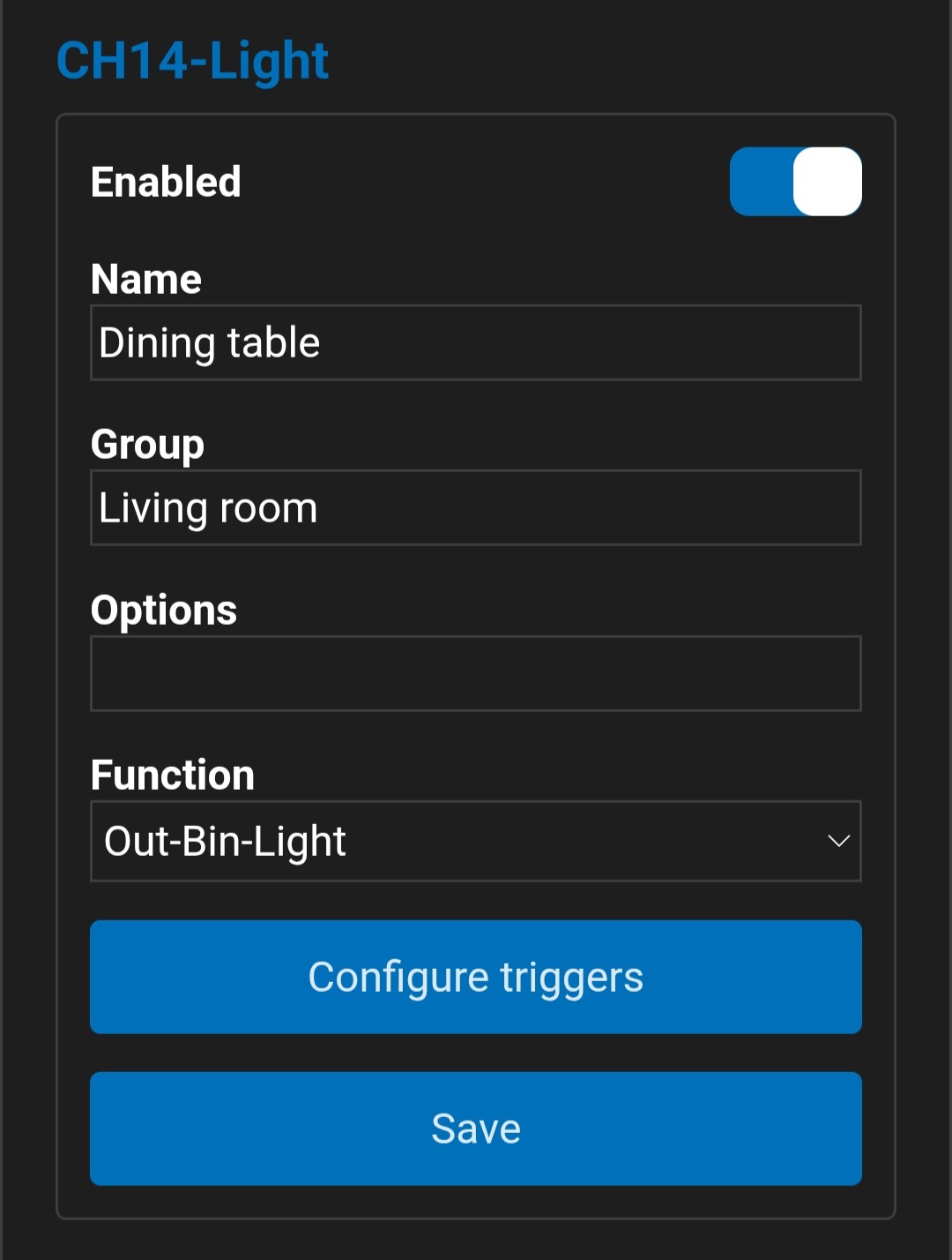 |
Configure Triggers
Triggers configureren
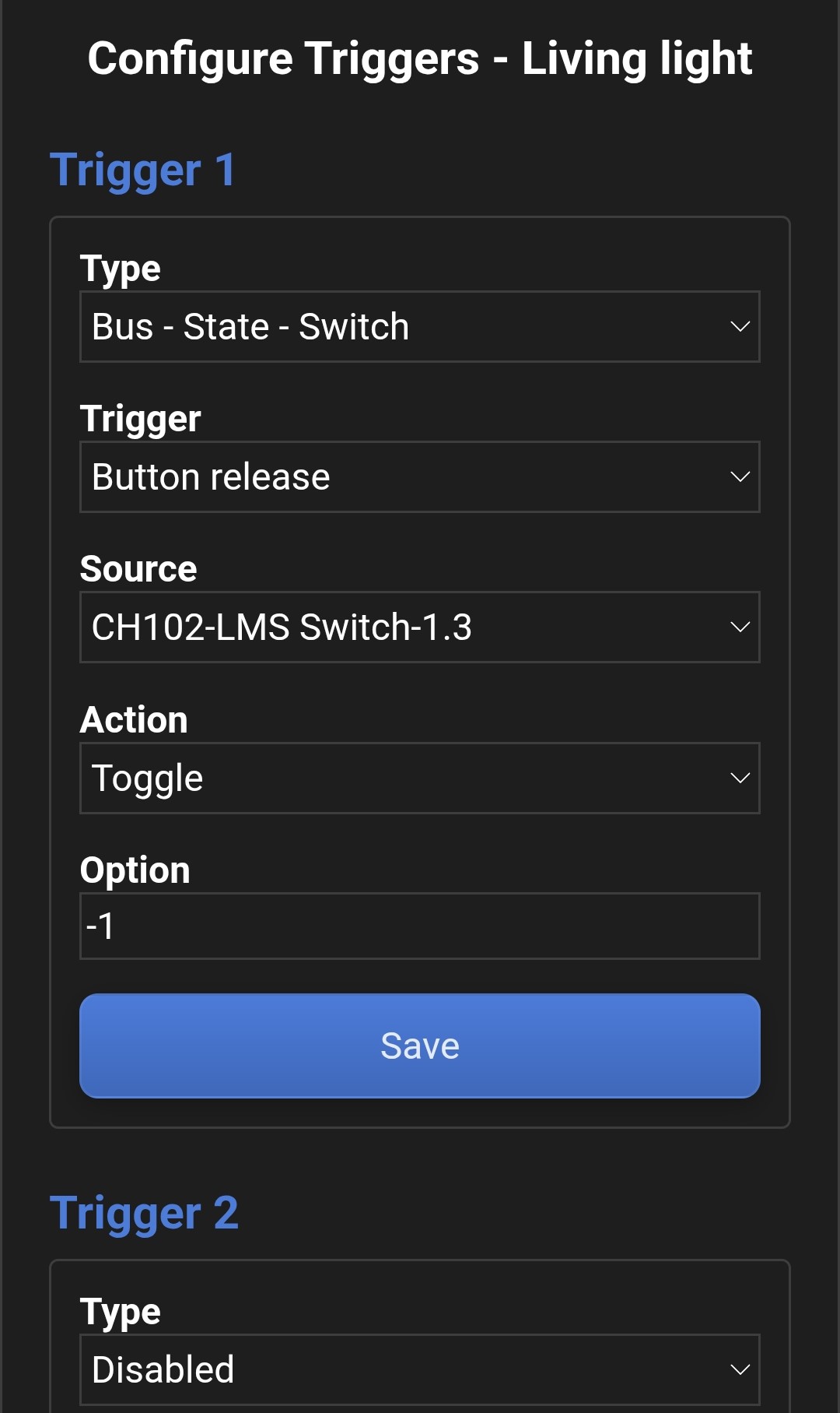
Triggers are the foundation of programming. Up to 12 triggers can be configured for each output. When a trigger is activated, a configurable action is executed on the corresponding output. In the simplest form, you can link up to 12 push-buttons to a single output. However, much more is possible thanks to support for different trigger types and actions. An overview is shown below.
Triggers vormen de basis van de programmering. Voor elke uitgang kunnen tot 12 triggers geconfigureerd worden. Bij activering van een trigger wordt er een configureerbare actie op de betreffende uitgang uitgevoerd. In de eenvoudigste vorm koppel je zo tot 12 drukknoppen aan één lichtpunt. Er is echter veel meer mogelijk dankzij ondersteuning voor verschillende triggertypes en acties. Hieronder een overzicht.
Trigger Types
Triggertypes
- Pushbutton events
- State of sensors and actuators
- Value of sensors and actuators
- Scenes
- Time
- Sunrise or sunset
- Drukknop events
- Status van sensoren en actuatoren
- Waarde van sensoren en actuatoren
- Sferen
- Tijd
- Zonsopgang of zonsondergang
Trigger Actions
Triggeracties
- Turn on, turn off, or toggle
- Turn on with delayed turn-off
- Set value (for dimmers, screens, etc.)
- Dim value (for dimmers, screens, etc.)
- Inschakelen, uitschakelen of toggle
- Inschakelen met uitschakelvertraging
- Waarde instellen (voor dimmers, screens, etc.)
- Waarde dimmen (voor dimmers, screens, etc.)
| Instelling | Dashboard → Configuration → Channel Configuration → Configure Triggers |
|---|---|
| Type |
Preset based on trigger type
|
| Trigger |
Trigger to be linked to an action
|
| Source |
Trigger source. Modules and associated channels are detected automatically (auto-discovery). (*3)
|
| Action |
Action to execute when the trigger occurs
|
| Option |
Additional parameter, depending on the selected action and output type
|
| Scene |
Action executed when this scene command is received
|
| Value |
Reference value for greater than, less than, and equal to triggers
|
| Time |
Execute action at this time
|
| Days |
Execute time-based triggers only on the selected days
|
| Save | Save the settings above |
| Preview |
|
| Instelling | Dashboard → Configuration → Channel Configuration → Configure Triggers |
|---|---|
| Type | Voorselectie op basis van type
|
| Trigger | Trigger om aan een actie te koppelen
|
| Source | Bron van de trigger. Modules en bijbehorende kanalen worden automatisch gedetecteerd (autodiscovery). (*3)
|
| Action | Uit te voeren actie bij trigger
|
| Option | Extra parameter, afhankelijk van de actie en het uitgangstype
|
| Scene | Actie bij ontvangst van dit sfeercommando
|
| Value | Referentiewaarde voor groter dan, kleiner dan en gelijk aan-triggers
|
| Time | Actie uitvoeren op dit tijdstip
|
| Days | Tijdgebaseerde triggers enkel uitvoeren op deze dagen
|
| Save | Sla bovenstaande instellingen op |
| Weergave | |
(*2) Requires a network connection and correct location settings
(*3) Autodiscovery can take up to 2 minutes after modules boot; the list does not refresh automatically.
(*4) Normally, the Dim up/down action only changes brightness, but with Dim select HSV you can use the same dim action (push-button) to adjust saturation or color as well. The learning function links Dim select HSV to a Button release 2x, so a double-press determines whether dimming changes brightness, saturation, or color. The output will briefly turn off to indicate that the dim selection has changed. (*1) Niet combineren met multi‑press‑events
(*2) Vereist netwerkverbinding en correcte locatie‑instellingen
(*3) Autodiscovery kan tot 2 minuten duren na opstarten van modules; de lijst herlaadt niet automatisch.
(*4) Normaal wijzigt de Dim up/down actie enkel de helderheid, maar door Dim select HSV kan je met diezelfde dim actie (drukknop) ook de saturatie of kleur aanpassen. De leerfunctie koppelt Dim select HSV aan een Button release 2x, een dubbele druk bepaalt dus of de dimfunctie de helderheid, satuartie of kleur wijzigt. De uitgang zal kort even uitgaan om aan te geven dat de dimselectie is gewijzigd.
Configure Virtual Channels
Virtuele uitgangen configureren
Virtual channels are similar to normal channels, with a few exceptions. They have only a virtual (no physical) output, and can be configured to perform a logical function (AND, OR, XOR, NOT) or to send group or scene commands on the LumaLink bus.
Virtuele uitgangen zijn vergelijkbaar met normale uitgangen, met enkele uitzonderingen. Ze hebben enkel een virtuele (geen fysieke) uitgang, en kunnen bovendien geconfigureerd worden om een logische functie te vervullen (AND, OR, XOR, NOT) of om groep- of sfeercommando's op de LumaLink-bus te sturen.
Another use case is increasing the number of triggers for a physical output. For example: do you want to use 16 push-buttons to toggle one output, but the trigger limit is 12? Then learn part of the push-buttons on a virtual channel and use that as a trigger input for the physical output.
Een andere toepassing is het uitbreiden van het aantal triggers van een fysieke uitgang. Wil je bijvoorbeeld 16 drukknoppen gebruiken om één uitgang te schakelen, maar is de limiet op het aantal triggers 12? Leer dan een deel van de drukknoppen in op een virtuele uitgang en gebruik die als trigger-input voor de fysieke uitgang.
| ItemDashboard → Configuration → Virtual Channels | ItemDashboard → Configuration → Virtual Channels | ||
|---|---|---|---|
| Enabled | Channel in use (not used to switch the output on/off) | ||
| Enabled | Kanaal in gebruik (niet voor in- of uitschakelen van de uitgang) | ||
| Name | Optional name for the output | ||
| Name | Optionele naam voor uitgang | ||
| Group | Optional group name for the output
|
||
| Group | Optionele groepsnaam voor uitgang
|
||
| Options | Advanced channel options
|
||
| Options | Geavanceerde kanaalopties
|
||
| Function | Function of the virtual output
|
||
| Function | Functie van de virtuele uitgang
|
||
| Preview | 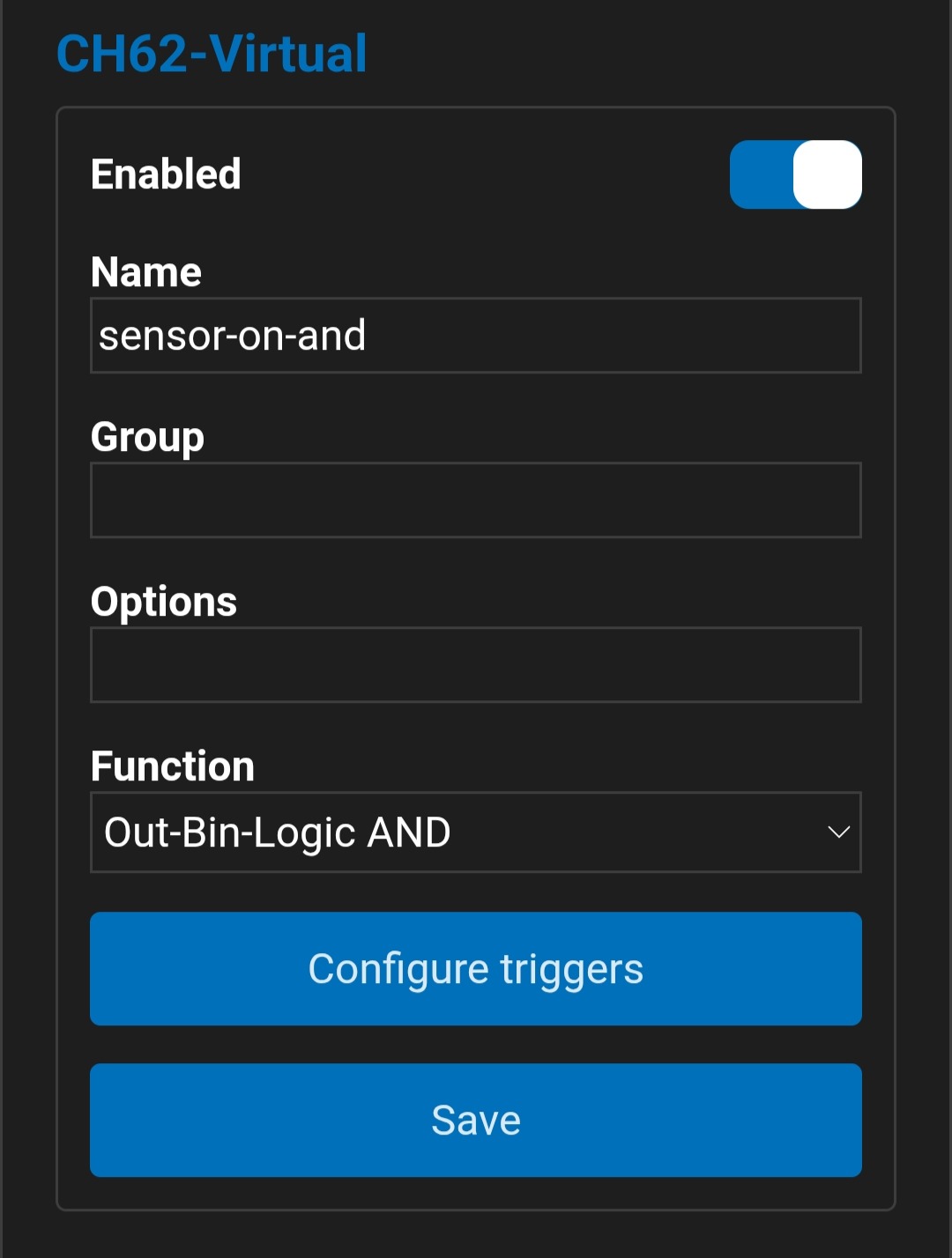 |
||
| Weergave | |
||
Logic gates (AND, OR, XOR, NOT)
Logische poorten (AND, OR, XOR, NOT)
By changing the function of a virtual channel to Logic AND/OR/XOR, the channel will perform the selected logic function. Where standard virtual outputs allow up to 12 triggers, here you can configure up to 12 inputs for the logic function.
Door de functie van een virtueel kanaal aan te passen naar Logic AND/OR/XOR, gaat het kanaal de betreffende logische functie vervullen. Waar je bij standaard virtuele uitgangen tot 12 triggers kunt configureren, kun je hier tot 12 ingangen voor de logische functie instellen.
The specific logic NOT function is not available as a separate mode, but it is also not required: logical inversion can be achieved in several ways.
De specifieke functie logic NOT is niet beschikbaar als aparte modus, maar is ook niet nodig: een logische inversie is op verschillende manieren mogelijk.
- Inputs can be inverted by, for example, replacing Status ON with Status OFF, Greater Than with Less Than, or Sunrise with Sunset.
- A virtual AND, OR, or XOR channel with a single trigger behaves like a buffer or an inverter. You obtain the inversion by inverting the input as described above.
- Ingangen kunnen geïnverteerd worden door bijvoorbeeld Status ON te vervangen door Status OFF, Greater Than door Less Than, of Sunrise door Sunset.
- A virtual AND, OR, or XOR channel with a single trigger behaves like a buffer or an inverter. You obtain the inversion by inverting the input as described above.
- Een virtueel AND‑, OR‑ of XOR‑kanaal met één enkele trigger gedraagt zich als buffer of inversie. De inversie verkrijg je door de ingang te inverteren zoals hierboven beschreven.
Controlling scenes
Sferen aansturen
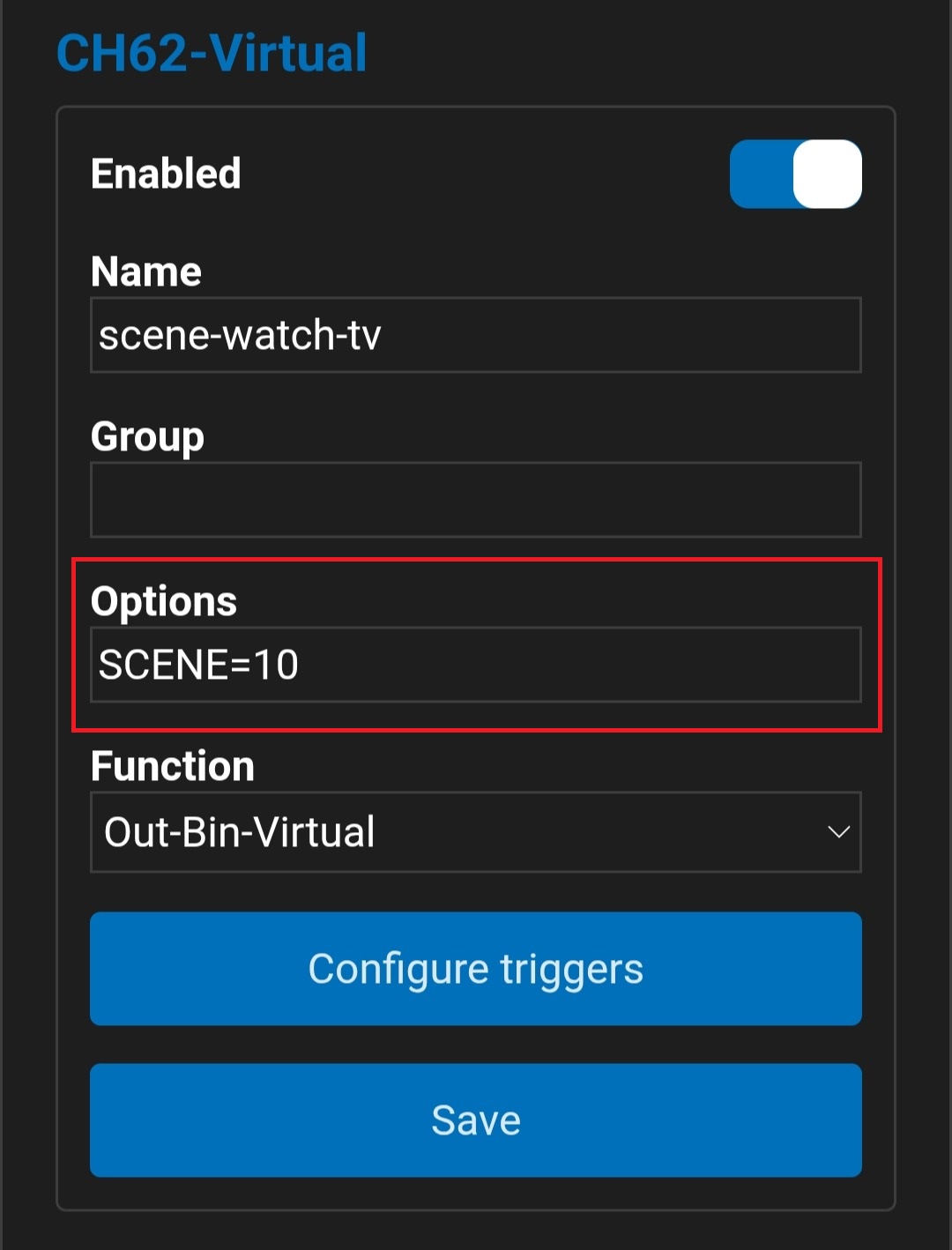
Virtual channels can send scene commands using the SCENE option. For example, SCENE=10 sends an "activate scene 10" command on the LumaLink bus on every toggle. All channels configured for this scene (trigger scene 10) will change state/value.
Virtuele kanalen kunnen sfeercommando's sturen met de optie SCENE. SCENE=10 stuurt bijvoorbeeld bij elke toggle een "activeer sfeer 10"‑commando op de LumaLink‑bus. Alle kanalen die voor deze sfeer geconfigureerd zijn (trigger sfeer 10) zullen van status/waarde veranderen.
Controlling groups
Groepen aansturen
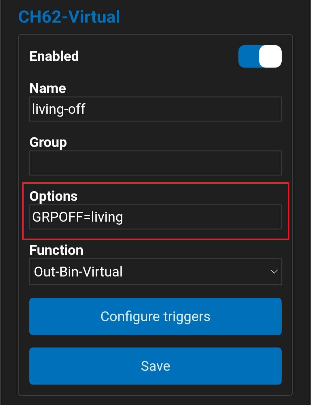
Virtual channels can send group on/off commands using the GRPON or GRPOFF options. For example, GRPON=living sends an activate group living command on the LumaLink bus on every toggle. All channels with living configured as the group name will switch on.
Virtuele kanalen kunnen groep‑aan/uitcommando's sturen met de opties GRPON of GRPOFF. GRPON=living stuurt bijvoorbeeld bij elke toggle een activeer groep living‑commando op de LumaLink‑bus. Alle kanalen waarbij living als groepsnaam is geconfigureerd, schakelen in.
Expanding the number of triggers
Aantal triggers uitbreiden
Virtual channels can be used to expand the number of triggers for physical outputs. In the example below, 16 push-buttons are linked to one output using a virtual channel: 12 push-buttons on the virtual channel, and the remaining 4 on the physical output. You then configure the virtual channel as an input (trigger) on the physical output. Important: this requires two triggers — Changed to ON and Changed to OFF — for the corresponding virtual channel.
Virtuele kanalen kunnen gebruikt worden om het aantal triggers van fysieke uitgangen uit te breiden. In het voorbeeld hieronder worden 16 drukknoppen aan één uitgang gekoppeld met behulp van een virtuele uitgang: 12 drukknoppen op de virtuele uitgang, de overige 4 op de fysieke uitgang. Het virtuele kanaal configureer je vervolgens als input (trigger) op de fysieke uitgang. Belangrijk: hiervoor zijn twee triggers nodig — Changed to ON en Changed to OFF — voor het betreffende virtuele kanaal.
Learning Mode
Leermodus
Learning mode allows you to automatically link triggers and actions to outputs (channels) based on push-button events.
De leermodus laat toe automatisch triggers en acties aan uitgangen (kanalen) te koppelen op basis van drukknop-events.
A channel can be put into learning mode using LumaConfig (see below) or using the manual controls on the module (see the technical manual). Only one channel can be in learning mode at a time. When you enable learning mode for a specific channel, learning mode on other channels will be terminated.
Een kanaal kan in leermodus gezet worden met LumaConfig (zie hieronder) of met handbediening op de module (zie technische handleiding). Er kan maar één kanaal tegelijk in leermodus staan. Wanneer je de leermodus voor een specifiek kanaal activeert, wordt de leermodus van andere kanalen uitgeschakeld.
| Setting | Dashboard → Configuration → Learning Mode |
|---|---|
| Instelling | Dashboard → Configuration → Learning Mode |
| Activate Learning | Enable learning mode for this channel
|
| Activate Learning | Leermode inschakelen voor dit kanaal
|
| Channel name | Turn this channel on/off
|
| Channel name | Dit kanaal aan/uit zetten
|
| Channel value | Change the channel value (e.g., brightness)
|
| Channel value | Kanaalwaarde wijzigen (bv. helderheid)
|
| Preview | 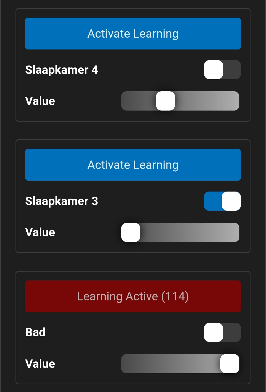 |
| Weergave | |
Link push-buttons
Drukknoppen koppelen
When linking push-buttons using learning mode, a button release trigger is automatically added with a toggle action. You can edit the trigger and action afterwards in the channel configuration.
Bij het koppelen van drukknoppen met de leermodus, wordt er automatisch een button release-trigger toegevoegd met toggle actie. Trigger en actie kun je nadien eventueel aanpassen in de kanaalconfiguratie.
- Enable learning mode for the desired output
- The activate button in LumaConfig turns red
- On the module, the output LED starts blinking
- Activeer de leermode voor de gewenste uitgang
- De activeer knop in LumaConfig kleurt rood
- Op de module begint de led van de uitgang te knipperen
- Press and hold the push-button you want to link until the output status changes.
- Typically press for 5 to 10 seconds
- Druk lang op de drukknop die je wilt gaan koppelen, dit tot de status van de uitgang verandert.
- Normaal 5 a 10 seconden drukken
- Press the push-button briefly again to confirm the link.
- You can press again to verify that the output is actually linked.
- Druk nog eens kort op de drukknop om de koppeling te bevestigen.
- Je kan nog eens drukken om te controleren of de uitgang daadwerkelijk gekoppeld is.
- In the background a new "Button release" trigger will be added to this output, you can edit it if required.
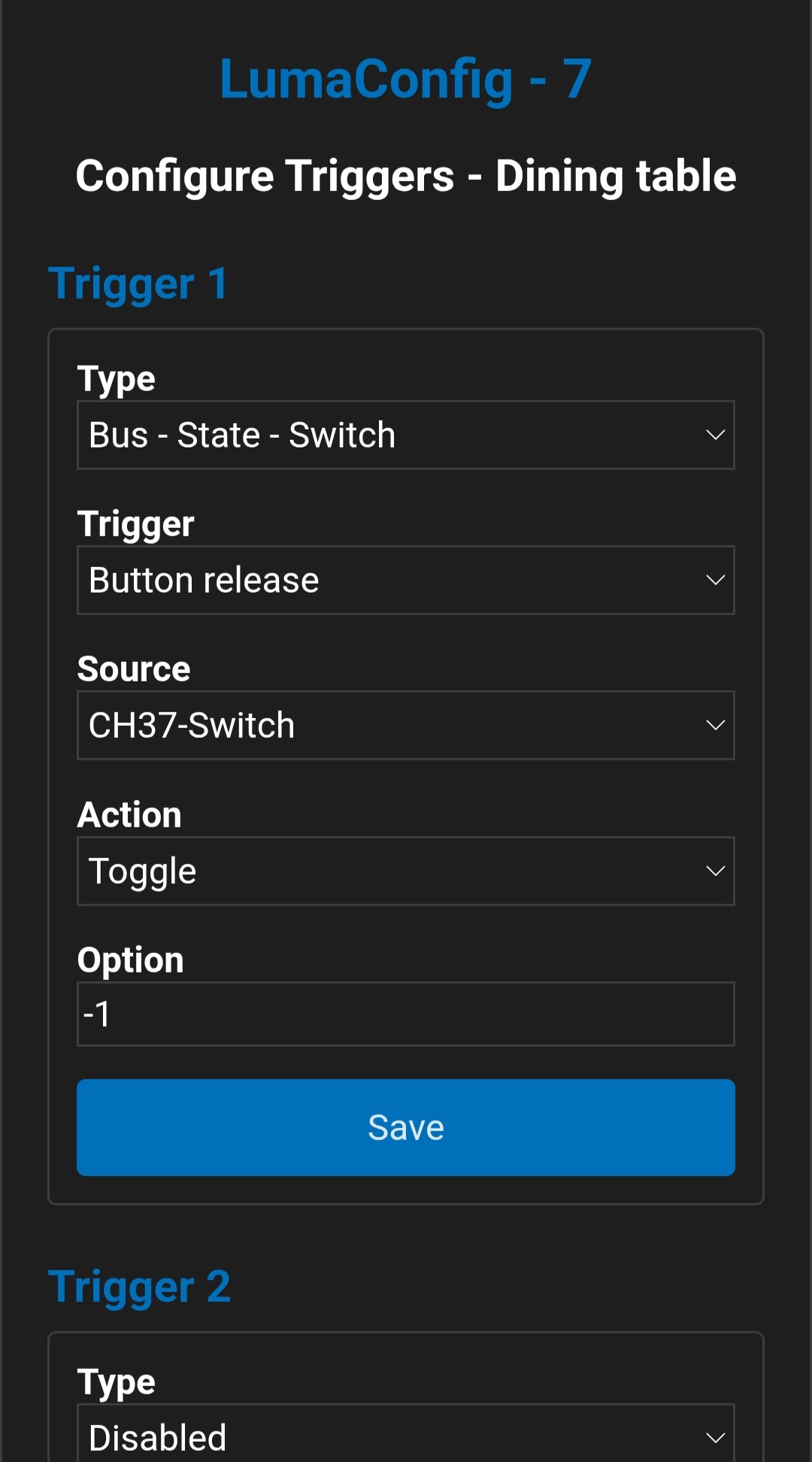
- Repeat this procedure from step 2 if you want to link additional push-buttons to the same output.
- Herhaal deze procedure vanaf stap 2 indien je nog drukknoppen wenst te koppelen aan dezelfde uitgang.
Dimmable outputs
Dimbare uitgangen
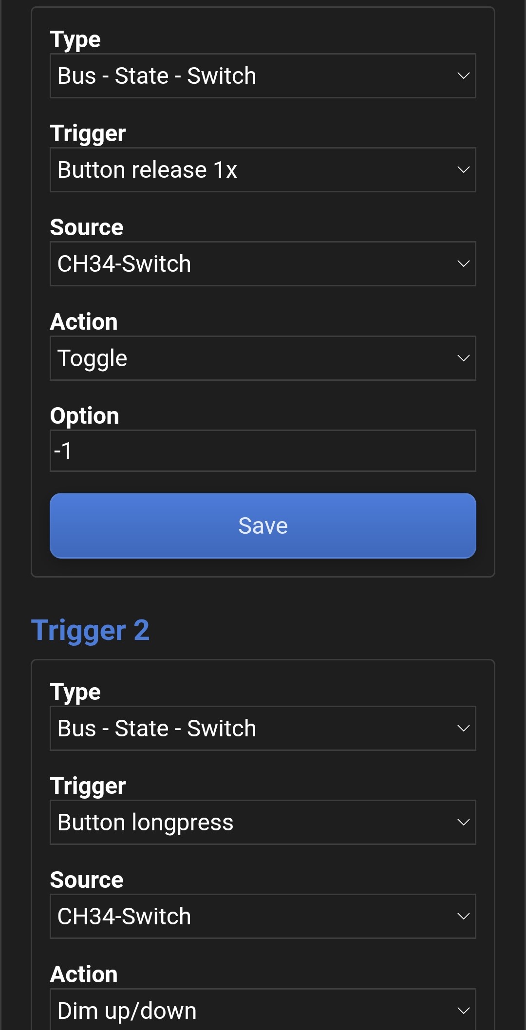
Dimmable outputs are configured in the same way as described above. However, a second trigger is added automatically to allow dimming using the same push-button. This trigger is configured as a "longpress" with the "Dim up/down" action. As a result, each dimmable output uses two triggers.
Dimbare uitgangen worden op dezelfde manier geconfigureerd als hierboven beschreven. Er wordt echter automatisch een tweede trigger toegevoegd om de uitgang met dezelfde drukknop te dimmen. Deze trigger gebruikt de gebeurtenis "longpress" in combinatie met de actie "Dim up/down". Hierdoor gebruikt elke dimbare uitgang twee triggers.
Unlinking push-buttons
Drukknoppen ontkoppelen
When unlinking push-buttons using learning mode, the corresponding triggers are automatically removed from the channel configuration. Tip: in many cases it is faster to unlink a push-button manually in the channel configuration, especially if the address and channel of the push-button are already known.
Bij het ontkoppelen van drukknoppen met de leermodus, worden de desbetreffende triggers automatisch verwijderd uit de kanaalconfiguratie. Tip: in veel gevallen is het sneller om manueel de drukknop te ontkoppelen in de kanaalconfiguratie, zeker als het adres en kanaal van de drukknop al gekend zijn.
-
Activate learning mode for the desired output
- The activate button in LumaConfig turns red
- The LED of the output on the module starts blinking
-
Activeer de leermode voor de gewenste uitgang
- De activeer knop in LumaConfig kleurt rood
- Op de module begint de led van de uitgang te knipperen
-
Press and hold the push-button you want to unlink.
After 5 to 10 seconds the status will change; ignore this and keep pressing
until the status changes again. This may take some time.
- Typically 20 to 60 seconds, depending on the output type
-
Druk lang op de drukknop die je wilt gaan ontkoppelen.
Na 5 a 10 seconden verandert de status, negeer dit,
blijf drukken tot de status nogmaals verandert, dit kan even duren.
- Normaal 20 a 60 seconden drukken (afhankelijk van type uitgang)
-
Press the push-button briefly once more to confirm the unlinking.
- You can press again to verify that the output has indeed been unlinked.
-
Druk nog eens kort op de drukknop om de ontkoppeling te bevestigen.
- Je kan nog eens drukken om te controleren of de uitgang daadwerkelijk ontkoppeld is.
- Repeat this procedure starting from step 2 if you want to unlink additional push-buttons.
- Herhaal deze procedure vanaf stap 2 indien je nog drukknoppen wenst te ontkoppelen.
LumaLink Tools
LumaLink-tools
Bus logger
Bus-logger
The LumaLink bus logger is a useful debug tool that shows bus communication live. This can help, for example, to find specific addresses.
De LumaLink-buslogger is een handige debugtool die live de buscommunicatie kan weergeven. Dit is bijvoorbeeld nuttig om bepaalde adressen te achterhalen.
| Item | Dashboard → Configuration → Learning Mode |
|---|---|
| Item | Dashboard → Configuration → Learning Mode |
| Status Messages | Show LumaLink status messages on the bus |
| Status Messages | Toon LumaLink-statusberichten op de bus |
| Event Messages | Show LumaLink event messages on the bus |
| Event Messages | Toon LumaLink-eventberichten op de bus |
| Filter Address | Show LumaLink messages from a specific module
|
| Filter Address | Toon LumaLink-berichten van een specifieke module
|
| Filter Channel | Show LumaLink messages for a channel
|
| Filter Channel | Toon LumaLink-berichten van een kanaal
|
| Log Output | Log window; see numbering in the screenshot.
|
| Log Output | Logvenster, zie nummering bij weergave.
|
| Clear Output | Clear the log window |
| Clear Output | Logvenster leegmaken |
| Preview | 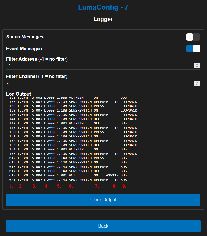 |
| Weergave | |
Scene and group tester
Scene‑ en groep‑tester
This tool allows you to send LumaLink scene or group commands directly. Use it, for example, to verify that the desired outputs respond to a specific scene or group.
Deze tool laat je toe om rechtstreeks LumaLink sfeer‑ of groepscommando's te versturen. Gebruik dit bijvoorbeeld om te verifiëren of de gewenste uitgangen reageren op een bepaalde sfeer of groep.
| Item | Dashboard → Configuration → LumaLink Tools |
|---|---|
| Item | Dashboard → Configuration → LumaLink Tools |
| Scene | Scene you want to activate with the Send button.
|
| Scene | Sfeer die je wilt activeren met de Send-knop.
|
| Group | Group you want to (de)activate with the Send button.
|
| Group | Groep die je wilt (de)activeren met de Send-knop.
|
| Preview | 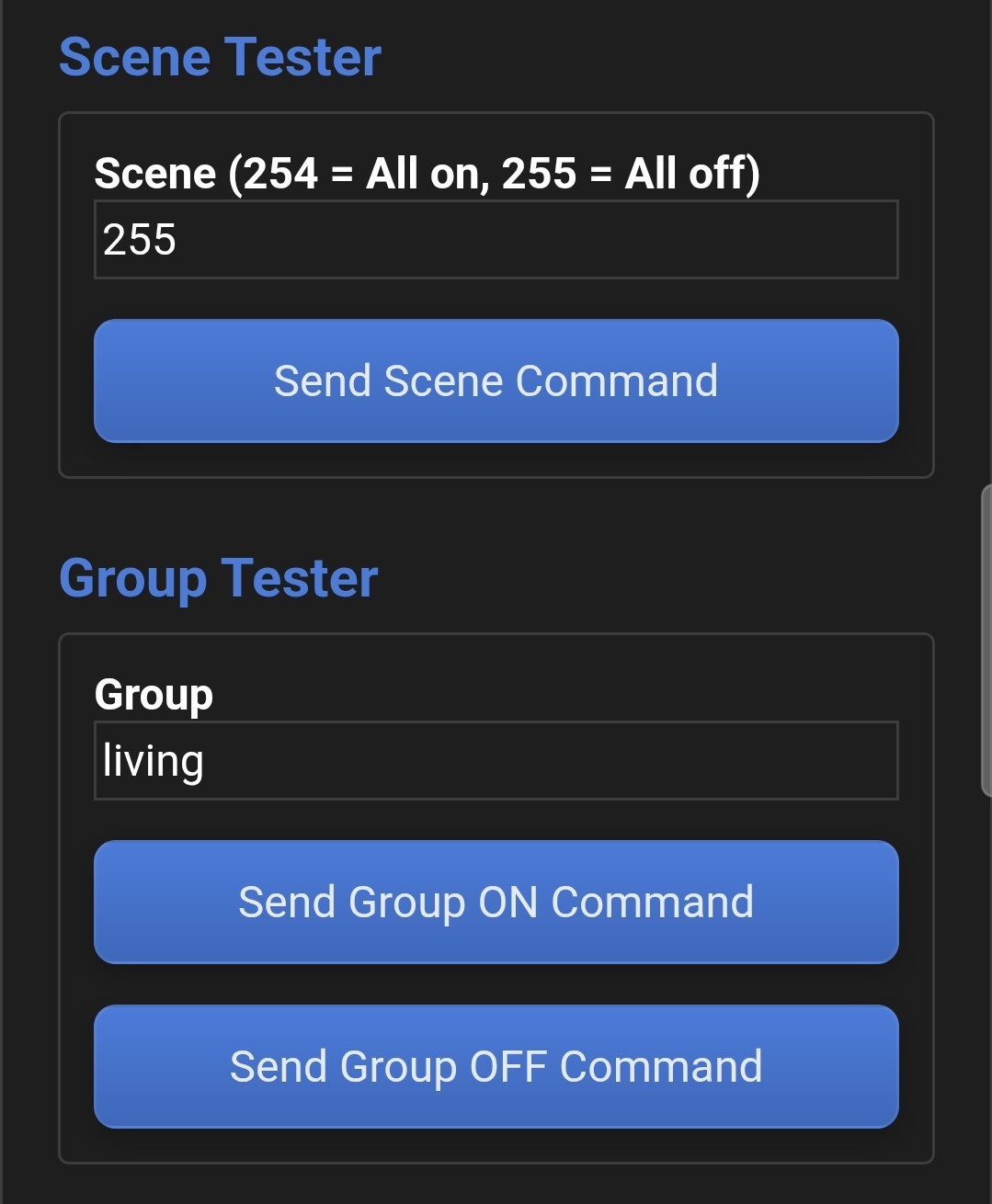 |
| Weergave | |
Module information
Module-informatie
Module information provides an overview of the module's hardware and software status.
De modue-informatie geeft je een overzicht van de hardware- en software status van de module.
ℹ️ Information
ℹ️ Informatie
Module information is not refreshed automatically, you can force an update using the "Refresh" button at the bottom.
Module-informatie wordt niet automatisch vernieuwd, dit kun je wel forceren met de knop Refresh onderaan.
| Device | Dashboard → Configuration → Information |
|---|---|
| Device | Dashboard → Configuration → Information |
| Hardware | Module type and firmware version |
| Hardware | Moduletype en firmwareversie |
| Software | LumaControl software version |
| Software | LumaControl softwareversie |
| Serial number | Serial number (if known) |
| Serial number | Serienummer indien bekend |
| Module temperature | Internal temperature |
| Module temperature | Interne temperatuur |
| Module voltage | Internal supply voltage |
| Module voltage | Interne voedingsspanning |
| Module status | Module status
|
| Modulestatus | Module status
|
| Network | |
| Network | |
| Gateway | Assigned IPv4 gateway (router) |
| Gateway | Toegewezen IPv4-gateway (router) |
| Netmask | Assigned IPv4 netmask |
| Netmask | Toegewezen IPv4-netmasker |
| IPv4 | Assigned IPv4 address |
| IPv4 | Toegewezen IPv4-adres |
| MAC address | Unique MAC address of the module |
| MAC | Uniek MAC-adres van de module |
| LumaLink | |
| LumaLink | |
| Bus address | LumaLink bus address
|
| Bus address | LumaLink busadres
|
| Bus state | LumaLink bus status
|
| Bus state | LumaLink busstatus
|
| Error count | LumaLink error counter |
| Error count | LumaLink errorteller |
| MQTT | |
| MQTT | |
| State | MQTT status
|
| State | MQTT-status
|
| Error count | MQTT error counter |
| Error count | MQTT errorteller |
| Time (*1) | |
| Time (*1) | |
| Local time | Current date and time according to the internal clock |
| Local time | Huidige datum en tijd volgens de interne klok |
| Sunrise | Today's sunrise according to the internal astro clock |
| Sunrise | Huidige zonsopgang volgens de interne astroklok |
| Sunset | Today's sunset according to the internal astro clock |
| Sunset | Huidige zonsondergang volgens de interne astroklok |
| Uptime | Time elapsed since the last restart |
| Uptime | Verstreken tijd sinds de laatste (her)start |
| Other | |
| Other | |
| Ping errors | Network watchdog error counter |
| Ping errors | Netwerk watchdog errorteller |
| Reset count | Number of unexpected resets |
| Reset count | Aantal onverwachte resets |
| Preview | 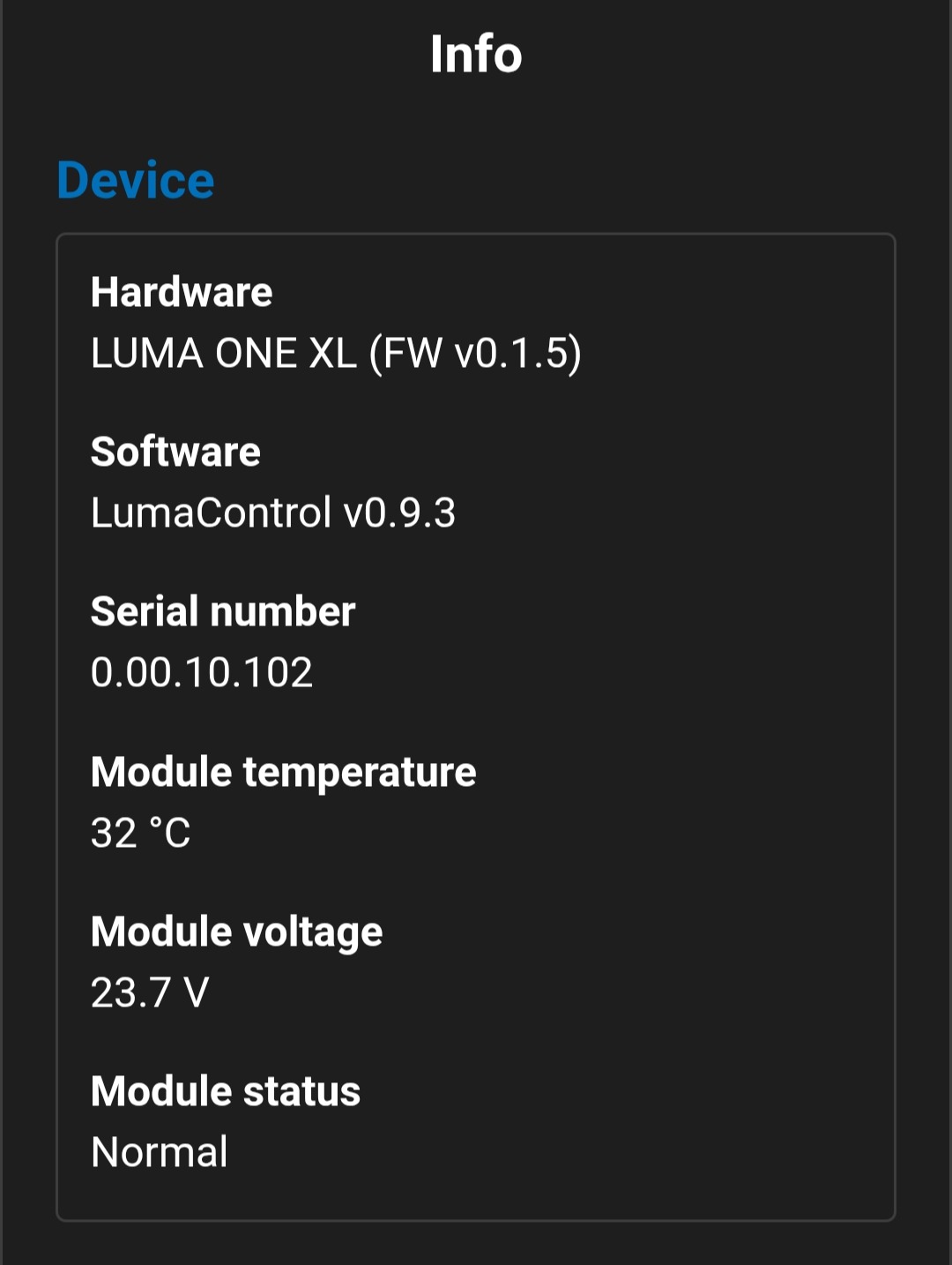 |
| Weergave | |
Other
Overige
Module options
Moduleopties
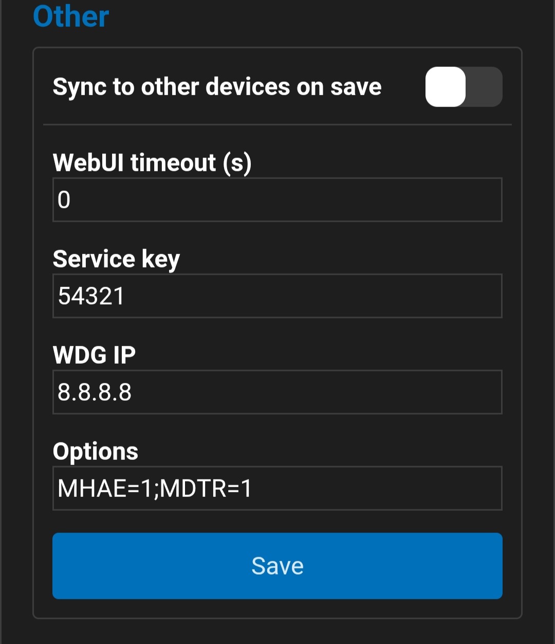
Below is a list of advanced module options. Multiple options are possible when separated with ";". A module restart is required before these options become active.
Hieronder vind je een lijst met geavanceerde moduleopties. Meerdere opties zijn mogelijk indien gescheiden met ";". Een herstart van de module is nodig voordat deze opties actief worden.
| Option | Dashboard → Configuration → Module Configuration → Other → Options | ||
|---|---|---|---|
| Optie | Dashboard → Configuration → Module Configuration → Other → Options | ||
| Home Assistant support |
MHAE — Module Home Assistant Enable
|
Home Assistant ondersteuning |
MHAE — Module Home Assistant Enable
|
| NTP time server |
MNTP — Module NTP
|
NTP tijdserver |
MNTP — Module NTP
|
| Disable triggers |
MDTR — Module Disable Triggers
|
Triggers uitschakelen |
MDTR — Module Disable Triggers
|
| Display |
|
Weergave |
|
Channel options
Kanaalopties
ℹ️ Information
ℹ️ Informatie
For multi-color fixtures, the module automatically converts brightness, saturation, and color values to red, green, blue, and white outputs.
Voor multi-colorarmaturen zet de module automatisch helderheid/saturatie/kleur om naar rood/groen/blauw/wit.
Below is a list of advanced channel options. Multiple channel options are possible when separated with ";". A module restart is required before these options become active.
Hieronder vind je een lijst met geavanceerde kanaalopties. Meerdere kanaalopties zijn mogelijk indien gescheiden met ";". Een herstart van de module is nodig voordat deze opties actief worden.
| Option | Dashboard → Configuration → (Virtual) Channel Configuration → Options | ||
|---|---|---|---|
| Optie | Dashboard → Configuration → (Virtual) Channel Configuration → Options | ||
| Blind/shutter run time |
BRUN — Blinds RUNtime
|
Looptijd screen/rolluik |
BRUN — Blinds RUNtime
|
| Invert output |
INV — INVert
|
Uitgang inverteren |
INV — INVert
|
| Default on |
DEFON — DEFault ON
|
Standaard aan |
DEFON — DEFault ON
|
| Default value |
DEFV — DEFault Value
|
Standaardwaarde |
DEFV — DEFault Value
|
| Status message interval (s) |
STATIV — STATus InterVal
|
Interval statusbericht (s) |
STATIV — STATus InterVal
|
| Ignore all on scene |
IGAON — IGnore All ON
|
Negeer alles aan sfeer |
IGAON — IGnore All ON
|
| Ignore all off scene |
IGAOFF — IGnore All OFF
|
Negeer alles uit sfeer |
IGAOFF — IGnore All OFF
|
| Fade on switch-on |
DFU — Dimmer Fade Up
|
Fade bij inschakelen |
DFU — Dimmer Fade Up
|
| Fade on switch-off |
DFD — Dimmer Fade Down
|
Fade bij uitschakelen |
DFD — Dimmer Fade Down
|
| Minimum dim level |
DBRM — Dimmer BRightness Minimum
|
Minimale dimwaarde |
DBRM — Dimmer BRightness Minimum
|
| LumaLink group off command |
GRPOFF — GRouP OFF
|
LumaLink groep uit-commando |
GRPOFF — GRouP OFF
|
| LumaLink group on command |
GRPON — GRouP ON
|
LumaLink groep aan-commando |
GRPON — GRouP ON
|
| LumaLink scene activate command |
SCENE — Activate scene
|
LumaLink sfeer activeren-commando |
SCENE — SCENE activeren
|
| Force Flex IO dimmer mode |
PWM10V — PWM or 10V mode
|
Flex IO dimmermodus forceren |
PWM10V — PWM of 10V modus
|
| Preview |
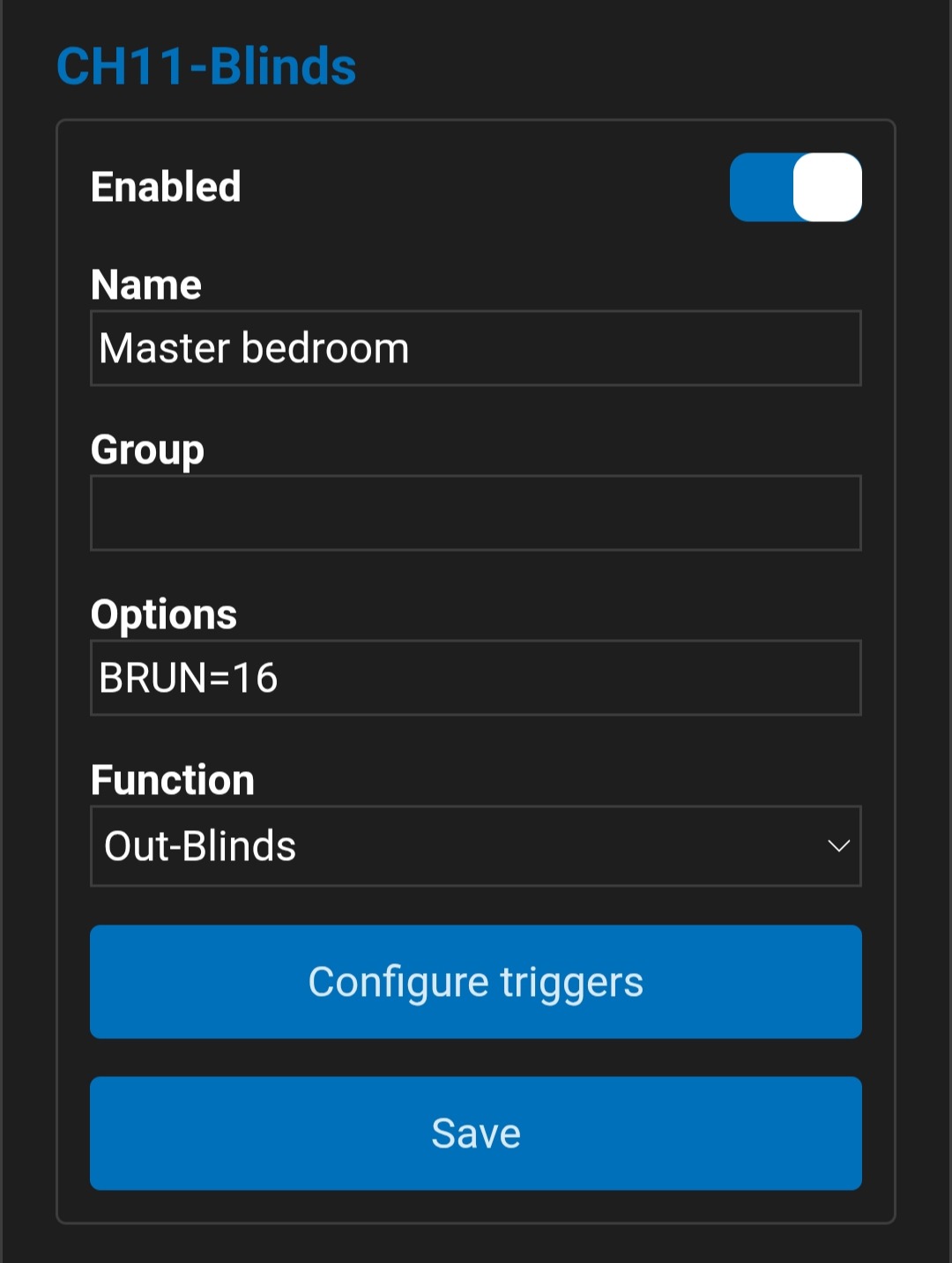
|
Weergave |
|
Background color
Achtergrondkleur
Normally, the LumaConfig background is not colored, but in some cases the background or border color changes in order to warn the user.
Normaal is de achtergrond van LumaConfig niet gekleurd, maar in sommige gevallen kan de achtergrond- en randkleur veranderen om de gebruiker te waarschuwen.
A red border and background indicates that the connection to the module has been lost (this may also occur while the module is restarting). An orange border indicates that a module restart is required, for example after changing module settings.
Een rode rand en achtergrond geeft aan dat de verbinding met de module is weggevallen (dit kan ook tijdens het herstarten van de module voorkomen). Een oranje rand geeft dan weer aan dat er een module herstart nodig is, dit kan bijvoorbeeld voorkomen als er module instellingen zijn gewijzigd.
Appendix
Appendix
Overzicht kanaalfuncties
Channel function overview
Voor de Flex IO's en relaisuitgangen, kan de kanaalfunctie aangepast worden. Overige kanalen zoals de vaste drukknopingangen (Pushbutton Inputs CH33-CH52), de optische ingang (CH5), CH10 en drukknoppen aangesloten op een LumaSense drukknopinterfaces krijgen automatisch de functie In-Bin-Switch toegewezen, dit is niet te wijzigen.
For the Flex IOs and relay outputs, the channel function can be changed. Other channels—such as the push-button inputs (Pushbutton Inputs), the optical input (CH5), CH10, and push-buttons connected via a LumaSense push-button interface automatically get the In-Bin-Switch function. This cannot be changed.
| Functie | Function | Flex IO's | Flex IOs | Relais | Relays | Beschrijving | Description |
|---|---|---|---|---|---|---|---|
| In-Bin-Generic | ✔ | ✔ | ✖ | ✖ |
Generic binary input (on/off)
|
Generieke binaire ingang (aan/uit)
|
|
| In-Bin-Switch | ✔ | ✔ | ✖ | ✖ |
Identical to In-Bin-Generic, but with push-button events
|
Identiek aan In-Bin-Generic, maar met drukknop events
|
|
| In-Pulse-Count | ✔ | ✔ | ✖ | ✖ |
Generic pulse counter input (S0)
|
Generieke pulsteller ingang (S0)
|
|
| In-Utility-Elec-Energy | ✔ | ✔ | ✖ | ✖ |
Pulse counter input (S0) with kWh conversion
|
Pulsteller ingang (S0), met kWh conversie
|
|
| In-0-10V | ✔ | ✔ | ✖ | ✖ | Input for reading 0-10 V signals | Ingang om 0-10V signalen uit te lezen | |
| Out-Bin-Generic | ✔ | ✔ | ✔ | ✔ |
Generic binary output
|
Generieke binaire uitgang
|
|
| Out-Bin-Light (*1) | ✔ | ✔ | ✔ | ✔ | Identical to Out-Bin-Generic | Identiek aan Out-Bin-Generic | |
| Out-0-10V | ✔ | ✔ | ✖ | ✖ |
Generic 0-10 V output
|
Generieke 0-10V uitgang
|
|
| Out-Dimmer (*1) | ✔ | ✔ | ✖ | ✖ |
PWM dimmer
|
PWM dimmer
|
|
| Out-Dimmer 0-10V (*1) | ✔ | ✔ | ✖ | ✖ |
0-10 V dimmer
|
0-10V dimmer
|
|
| Out-Dimmer CT (*1) | ✔ | ✔ | ✖ | ✖ |
Cold-warm white PWM dimmer
|
Koud-warm wit PWM Dimmer
|
|
| Out-Dimmer RGB (*1) | ✔ | ✔ | ✖ | ✖ |
RGB PWM dimmer
|
RGB PWM Dimmer
|
|
| Out-Dimmer RGBW (*1) | ✔ | ✔ | ✖ | ✖ |
RGBW PWM dimmer
|
RGBW PWM Dimmer
|
|
| Out-Blinds | ✖ | ✖ | ✔ | ✔ |
Control of blinds, screens, or similar motors
|
Aansturen rolluiken, screens of gelijkaardige motoren
|
|
| Out-Blinds H-bridge | ✖ | ✖ | ✔ | ✔ |
Control of blinds, screens, or similar motors
|
Aansturen rolluiken, screens of gelijkaardige motoren
|
DMX512 ↔ LumaLink mapping
DMX512 ↔ LumaLink mapping
| DMX-kanaal | DMX channel | LumaLink-kanaal | LumaLink channel | Dimmer RGB(W) | Dimmer RGB(W) | Dimmer CT | Dimmer CT | Dimmer (single color) | Dimmer (single color) |
|---|---|---|---|---|---|---|---|---|---|
| 1 | 1 | 23 | 23 | Rood A | Red A | Koud wit A | Cool white A | Single color A | Single color A |
| 2 | 2 | 24 | 24 | Groen A | Green A | Warm wit A | Warm white A | Single color B | Single color B |
| 3 | 3 | 25 | 25 | Blauw A | Blue A | Koud wit B | Cool white B | Single color C | Single color C |
| 4 | 4 | 26 | 26 | Wit A (enkel RGBW) | Wit A (enkel RGBW) | Warm wit B | Warm white B | Single color D | Single color D |
| 5 | 5 | 27 | 27 | Rood B | Red B | Koud wit C | Cool white C | Single color E | Single color E |
| 6 | 6 | 28 | 28 | Groen B | Green B | Warm wit C | Warm white C | Single color F | Single color F |
| 7 | 7 | 29 | 29 | Blauw B | Blue B | Koud wit D | Cool white D | Single color G | Single color G |
| 8 | 8 | 30 | 30 | Wit B (enkel RGBW) | Wit B (enkel RGBW) | Warm wit D | Warm white D | Single color H | Single color H |
| 9 | 9 | 31 | 31 | / | / | Koud wit E | Cool white E | Single color I | Single color I |
| 10 | 10 | 32 | 32 | / | / | Warm wit E | Warm white E | Single color J | Single color J |
For multi-color outputs, master and slave channels are used; the slave channels are partially read-only and follow the configuration of the master channel. In the table above, the master channels are shown in bold; this depends on the selected function.
Voor multi-color zijn er master- en slavekanalen; de slavekanalen zijn deels read-only en volgen de configuratie van het masterkanaal. In de tabel hierboven zijn de masterkanalen vet aangeduid; dit is afhankelijk van de functie.
Although slave channels are partially read-only, they can still be controlled. For RGB(W), the first slave channel (after the master) is the saturation channel and the second is the color channel. For CT, the first and only slave channel (after the master) is the color temperature channel. Triggers and actions (e.g. push-buttons) can also be linked to these slave channels using the standard method.
Hoewel slavekanalen deels read-only zijn, kunnen ze wel aangestuurd worden. Bij RGB(W) is het eerste slavekanaal (na master) het saturatie-kanaal en het tweede het kleur-kanaal. Bij CT is het eerste en enige slavekanaal (na master) het kleurtemperatuur-kanaal. Ook op deze slavekanalen kunnen triggers en acties gekoppeld worden (bijv. drukknoppen) volgens de gebruikelijke methode.
Example: you want to control one RGB fixture and two CT fixtures. Configure LumaLink channel 23 (DMX 1) for RGB. LumaLink channels 24 (saturation), 25 (color), and 26 are automatically assigned as slave channels of channel 23. For the CT fixtures, configure for example LumaLink channels 27 and 29 (DMX 5 and 7). LumaLink channels 28 and 30 (both color temperature) will then automatically become slave channels of channels 27 and 29 respectively.
Voorbeeld: je wilt 1 RGB-armatuur en 2 CT-armaturen aansturen. Configureer dan LumaLink-kanaal 23 (DMX 1) voor RGB. LumaLink-kanalen 24 (saturatie), 25 (kleur) en 26 worden automatisch slavekanalen van kanaal 23. Voor de CT-armaturen configureer je bijvoorbeeld LumaLink-kanalen 27 en 29 (DMX 5 en 7). LumaLink-kanalen 28 en 30 (beide kleurtemperatuur) worden dan automatisch slavekanalen van respectievelijk 27 en 29.
ℹ️ Information
ℹ️ Informatie
For multi-color fixtures, the module automatically converts brightness/saturation/color values to red/green/blue/white outputs.
Voor multi-colorarmaturen zet de module automatisch helderheid/saturatie/kleur om naar rood/groen/blauw/wit.
Module statistieken
Module statistics
De statistieken die de module zelf bijhoudt, hebben vooral betrekking op de levensduur en/of betrouwbaarheid van de module. Op deze manier willen we onze impact op de elektronische afvalberg zo klein mogelijk te houden. Bijvoorbeeld: een module waarvan er een relais uitgang defect is door heel intensief of foutief gebruik, hoeft niet vervangen te worden als de overige relaisuitgangen nog ver van hun minimale schakelcycli verwijderd zijn.
The statistics stored by the module are mainly intended to assess the service life and/or reliability of the module. This helps us to keep our impact on electronic waste as small as possible. For example: a module with one relay output damaged due to very intensive or incorrect use does not necessarily need to be replaced if the remaining relay outputs are still far from their minimum switching cycle count.
| Statistic | Description |
|---|---|
| Statistiek | Beschrijving |
| stats_psu_err | Number of times the module supply voltage was too high or too low → check the external power supply. Aantal keer dat de voedingsspanning van de module te hoog of te laag was → controleer de externe voeding. |
| stats_overtemp_err |
Number of times the module temperature was too high.
Aantal keer dat de moduletemperatuur te hoog was.
|
| stats_run_hrs_tot | Module total operating hours counter. Bedrijfsurenteller van de module. |
| stats_run_hrs_+50C | Total operating hours above 50°C. Totaal aantal bedrijfsuren boven 50°C. |
| stats_run_hrs_+60C |
Total operating hours above 60°C.
Totaal aantal bedrijfsuren boven 60°C.
|
| stats_run_hrs_+70C |
Total operating hours above 70°C.
Totaal aantal bedrijfsuren boven 70°C.
|
| ch_cycles |
Total number of switching cycles of a relay output.
Totaal aantal gemaakte schakelcycli van een relaisuitgang.
|
| Example Voorbeeld |
[Header]
hdr_datetime,str=Fri May 29 14:14:08 2026 hdr_module_id,u32=0xef5b hdr_module_mac,str=ac1518983ee4 hdr_module_build,str=luma hdr_firmware_ver,str=0.9.8 [Statistics] stats_overtemp_err=16 stats_psu_err=6 stats_run_hrs_tot=217 stats_run_hrs_+50C=0 stats_run_hrs_+60C=0 stats_run_hrs_+70C=0 [Cycle counters] ch3_cycles=207 (Living blinds) ch4_cycles=232 (CH4-Light) |